Page 1436 of 4592
A00436
ON
4 (+)
BE6653
S05337
DI±224
± DIAGNOSTICSENGINE (1MZ±FE)
459 Author�: Date�:
1 Connect OBD II scan tool or TOYOTA hand±held tester, and read value of mass
air flow rate.
PREPARATION:
(a) Connect the OBD II scan tool or TOYOTA hand±held tester to the DLC3.
(b) Turn the ignition switch ON and push the OBD II scan tool or TOYOTA hand±held tester main switch
ON.
(c) Start the engine.
CHECK:
Read mass air flow rate on the OBD II scan tool or TOYOTA hand±held tester.
RESULT:
Type IType II
Mass air flow rate (gm/sec.)0.0271.0 or more
Type I Go to step 2.
Type II Go to step 5.
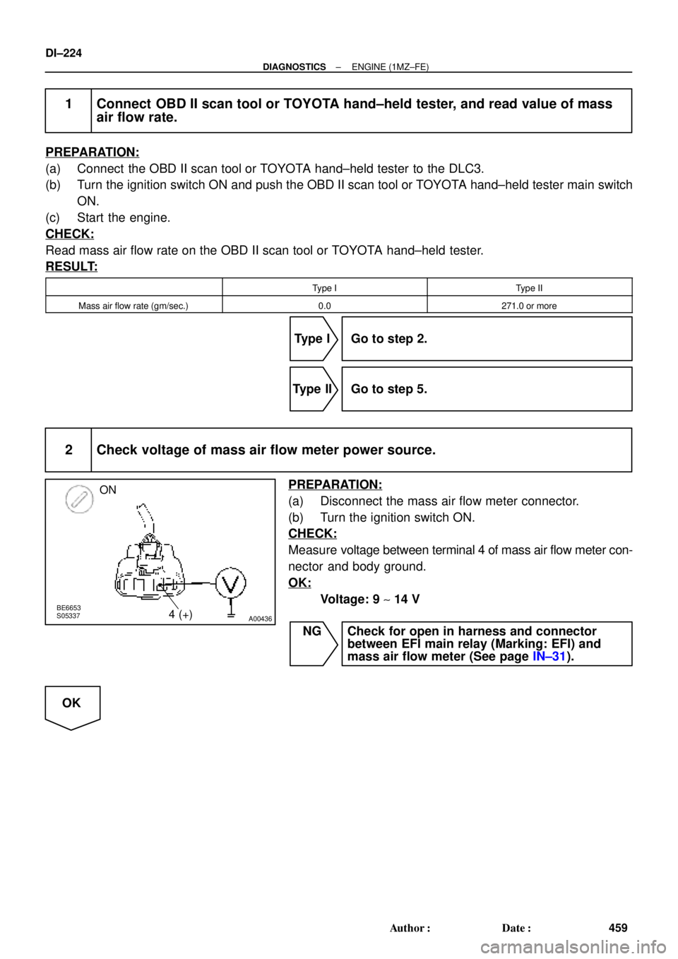
2 Check voltage of mass air flow meter power source.
PREPARATION:
(a) Disconnect the mass air flow meter connector.
(b) Turn the ignition switch ON.
CHECK:
Measure voltage between terminal 4 of mass air flow meter con-
nector and body ground.
OK:
Voltage: 9 ~ 14 V
NG Check for open in harness and connector
between EFI main relay (Marking: EFI) and
mass air flow meter (See page IN±31).
OK
Page 1457 of 4592

A07444
BatteryJunction Connector
MREL
ECM
B
B+
E1
E03
E03
E1E1
E03 OXL1
HTL1
OXR1
HTR
OXS
HTS
E8E8 E10 E11E7
E10
E10
E108
12
4
11
30
3
8
9
Y±R
3
2
4
1
W
BR
L±B
B
BR
3 2
4
1
B±Y
B±Y
B±Y
A A B Junction Connector
B
J28 J27
J27 B±YJunction Connector
2K
2J
3
1
2
5
EFI
2C 2A 1 5
F6
F4 1
1
B
W±B
EB
FL
MAINFusible
Link
Block
E03
Engine
Room
J/B
B±G
Heated Oxygen
Sensor
(Bank 1 Sensor 2)3
2
1
EDEC
P±BA
A
BR
BR4 B±YHeated Oxygen
Sensor
(Bank 1 Sensor 1)II3 B±WAC
J36 J35B±W
EFI Relay
BR
BR
2 7B±Y9
Heated Oxygen
Sensor
(Bank 2 Sensor 1)
D
± DIAGNOSTICSENGINE (1MZ±FE)
DI±245
480 Author�: Date�:
HINT:
After confirming DTC P0125, use the OBD II scan tool or TOYOTA hand-held tester to confirm voltage output
of the heated oxygen sensors (bank 1, 2 sensor 1) from CURRENT DATA.
If voltage output of the heated oxygen sensors (bank 1, 2 sensor 1) is less than 0.1 V, heated oxygen sensors
(bank 1, 2 sensor 1) circuit may be open or short.
WIRING DIAGRAM
INSPECTION PROCEDURE
HINT:
�If the vehicle run out fuel, the air±fuel ratio is LEAN and DTC P0125 will be recorded.
The MIL then comes on.
�Read freeze frame data using TOYOTA hand±held tester or OBD II scan tool. Because freeze frame
records the engine conditions when the malfunction is detected, when troubleshooting it is useful for
determining whether the vehicle was running or stopped, the engine warmed up or not, the air±fuel
ratio lean or rich, etc. at the time of the malfunction.
Page 1462 of 4592

A07445
B
BB B
2 142
31 23
4
BR
23
1
B±W P±BB B±WB±R
*
1L
E8 E8 E10 E10
E78 9 84 213 122011
AFR+
AFR±
AFL+
AFL± HAFR
OXS
HTS
MREL HAFLECM
3.3 V
3.3 V 3.0 V
3.0 V
E1
B+ E10 E10E10E10 1
J27
Engine Room J/B
F6
F4 2J
2A
2C2K
2
7
5 1
EFI Relay
1
1B
B±W
B±W
B EFI
1 2
2
52
22 3
L W±B1
1 2
A/F HTR
1
W
FL
MAIN FLEngine RoomBattery*
1B±W B
B
B±G
1
2 3
5
E04
E05
E03
*1B±R *1BR *G
*G
*B±W*L
ES1
J27 B
E
Junction
connector
A/F Sensor
(Bank 2, Sensor 1)
B±Y
A/F Sensor
(Bank 1, Sensor 2)
BRII1A
ABR
J22
Junction
Connector J24
Junction
Connector
B±Y
W±B
B±W
J35
J35J36A C
C
EB EC
A/F Sensor
(Bank 1, Sensor 1)
Engine Room
A/F HTR Relay
*: TMC Made
*: TMMK Made
Junction
Connector
4
to Analog±Digital
Converter
to Analog±Digital
Converter
DI±250
± DIAGNOSTICSENGINE (1MZ±FE)
485 Author�: Date�:
HINT:
�After confirming DTC P0125, use the OBD II scan tool or TOYOTA hand-held tester to confirm voltage
output of heated oxygen sensors (bank 1, 2 sensor 1) from CURRENT DATA.
�The ECM controls the voltage of AFR�, AFL�, AFR� and AFL� terminals of ECM to the fixed volt-
age. Therefore, it is impossible to confirm the A/F sensor output voltage without OBD II scan tool or
TOYOTA hand±held tester.
�OBD II scan tool (excluding TOYOTA hand±held tester) displays the one fifth of the A/F sensor output
voltage which is displayed on the TOYOTA hand±held tester.
WIRING DIAGRAM
Page 1476 of 4592
A02023
ON
HTL (+) HTR (+) HTS (+)
DI±264
± DIAGNOSTICSENGINE (1MZ±FE)
499 Author�: Date�:
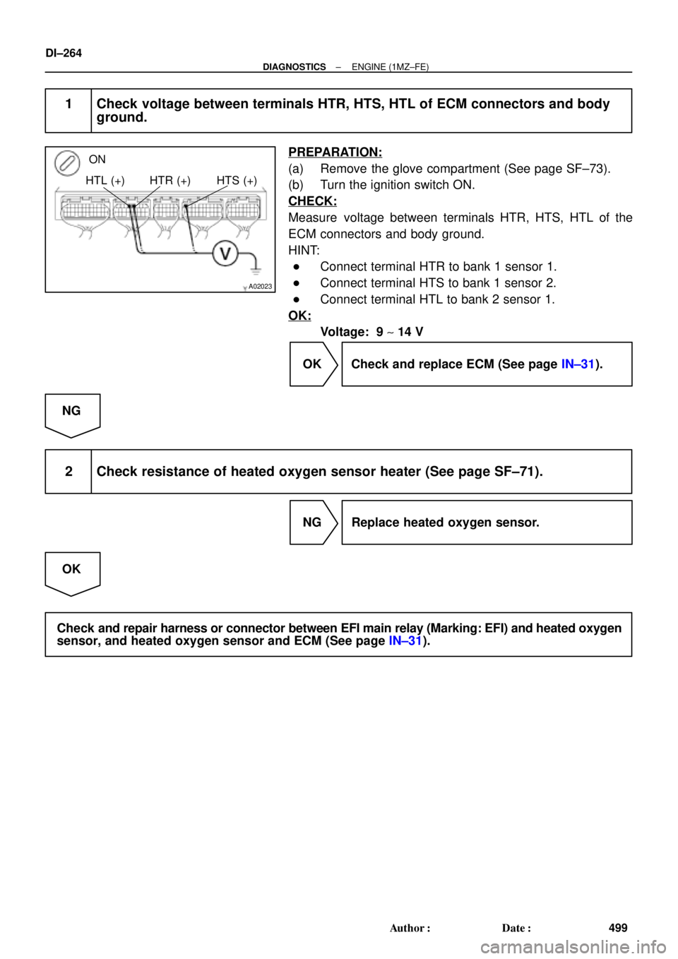
1 Check voltage between terminals HTR, HTS, HTL of ECM connectors and body
ground.
PREPARATION:
(a) Remove the glove compartment (See page SF±73).
(b) Turn the ignition switch ON.
CHECK:
Measure voltage between terminals HTR, HTS, HTL of the
ECM connectors and body ground.
HINT:
�Connect terminal HTR to bank 1 sensor 1.
�Connect terminal HTS to bank 1 sensor 2.
�Connect terminal HTL to bank 2 sensor 1.
OK:
Voltage: 9 ~ 14 V
OK Check and replace ECM (See page IN±31).
NG
2 Check resistance of heated oxygen sensor heater (See page SF±71).
NG Replace heated oxygen sensor.
OK
Check and repair harness or connector between EFI main relay (Marking: EFI) and heated oxygen
sensor, and heated oxygen sensor and ECM (See page IN±31).
Page 1505 of 4592
A07446
J20
Junction
Connector
EFI Relay
2K2J
2C
BB±YJ27 J28
W±B
EB
9B±Y Y±G
AA1218
13 1
2
G±Y
BRECM
EGR
E01
EGLS5 V
E2 32
VC
5 V
THG
E7
2
1W±GY
BR18
8
MREL
B+ BR
EGR Gas Temp. Sensor
E10 E10
22
E11 E10E11
Engine Room J/B
2A2
7 1
53
1 5
EFI
VSV
for EGR
B±Y
Junction
Connector
B
2
B±Y
J35
J35C
C Junction
ConnectorB±W
B±W
B±W
EGR Valve
Position Sensor
II3From
FL MAIN
S06906
Vehicle Speed
70 ~ 90 km/h
(43 ~ 56 mph)
Idling
IG SW OFF(1)(2)(3)
(4)(5)
Warmed up 3 ~ 5 min. 3 min. 3 ~ 5 min. 2 min.Time
± DIAGNOSTICSENGINE (1MZ±FE)
DI±293
528 Author�: Date�:
WIRING DIAGRAM
SYSTEM CHECK DRIVING PATTERN
Page 1524 of 4592

A07447
Vapor Pressure Sensor
2J2
9J23
B±Y
V
VSV for EVAP
LG
AA
2
1ECM
5V
VC
PTNK
E1
E2
EVP1
E01
E01
TPC
3
2
Engine Rom J/B
MREL VSV for Vapor
Pressure Sensor
II3
EB
B±W
W±BL±R Y
1BRE10
E7
E10
E72
17
18
7
9
E78
EFI Relay
IA1 L±RY Y
ID1 II13
5
1
II1 BR
BR
ID1 E10
B±Y
J28 J27
B
ID1 10
1
2
ID12 2A
7 1
2C5
2K 53
2
1 EFI
B±WFL MAIN
From
24
B+
J28E B±YB
B±Y
B±Y
V
J35
J35C
C Junction
Connector
Junction
ConnectorJunction
Connector DI±312
± DIAGNOSTICSENGINE (1MZ±FE)
547 Author�: Date�:
WIRING DIAGRAM
INSPECTION PROCEDURE
�If DTCs P0441, P0446, P0450 or P0451 is output after DTC P0440, first troubleshoot DTCs P0441,
P0446, P0450 or P0451. If no malfunction is detected, troubleshoot DTC P0440 next.
�Ask the customer whether, after the MIL came on, the customer found the fuel tank cap loose and tight-
ened it. Also ask the customer whether the fuel tank cap was loose when refuelling. If the fuel tank cap
was not loose, it was the cause of the DTC. If the fuel tank cap was not loose or if the customer was
not sure if it was loose, troubleshoot according to the following procedure.
�Read freeze frame data using TOYOTA hand±held tester or OBD II scan tool. Because freeze frame
records the engine conditions when the malfunction is detected, when troubleshooting it is useful for
determining whether the vehicle was running or stopped, the engine warmed up or not, the air±fuel
ratio lean or rich, etc. at the time of the malfunction.
�When the ENGINE RUN TIME in the freeze frame data is less than 200 seconds, carefully check the
VSV for EVAP, charcoal canister and vapor pressure sensor.
Page 1534 of 4592
DI±322
± DIAGNOSTICSENGINE (1MZ±FE)
557 Author�: Date�:
8 Check operation of VSV for EVAP (See page SF±58).
OK Go to step 9.
NG
Replace VSV and charcoal canister, and then clean the vacuum hoses between throttle body and
VSV for EVAP, and VSV for EVAP and charcoal canister.
9 Check for open and short in harness and connector between EFI main relay
(Marking: EFI) and VSV for EVAP, VSV for EVAP and ECM (See page IN±31).
NG Repair or replace harness or connector.
OK
Check and replace ECM (See page IN±31).
Page 1536 of 4592
A07146PTNK (+) E2 (±)
VSV Connector
for Vapor Pressure
Sensor
DI±324
± DIAGNOSTICSENGINE (1MZ±FE)
559 Author�: Date�:
12 Check for open and short in harness and connector between EFI main relay
(Marking: EFI) and VSV for vapor pressure sensor, and VSV for vapor pressure
sensor and ECM (See page IN±31).
NG Repair or replace harness or connector.
OK
Check and replace ECM (See page IN±31).
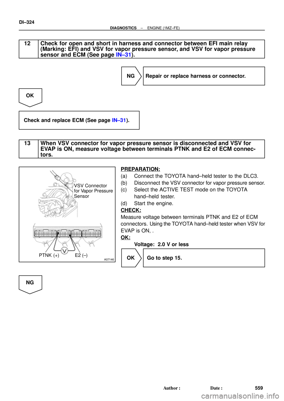
13 When VSV connector for vapor pressure sensor is disconnected and VSV for
EVAP is ON, measure voltage between terminals PTNK and E2 of ECM connec-
tors.
PREPARATION:
(a) Connect the TOYOTA hand±held tester to the DLC3.
(b) Disconnect the VSV connector for vapor pressure sensor.
(c) Select the ACTIVE TEST mode on the TOYOTA
hand±held tester.
(d) Start the engine.
CHECK:
Measure voltage between terminals PTNK and E2 of ECM
connectors. Using the TOYOTA hand±held tester when VSV for
EVAP is ON, .
OK:
Voltage: 2.0 V or less
OK Go to step 15.
NG