Page 1692 of 4592

D01897
Combination Meter
Ignition Switch Except California, w/ Engine Immobilizer and / or TRAC:
R
2
L8
11
6 C8
13
165
R±B
L±W YIJ1
IG310
1H
1VECM
1
E7
B+ 4
II2 P1
II3D J/C J2910 C8
C8O
Y
R±BY
R 2L
E7
E7
E10 II2 P1
P1
P1D D
J/C J29 E
15
14
B±W A
GR3
6CL±W (*1, *3)
O (*2, *4) LL
2L
RL R±L
J27J28
J/C
10FE E Y
Y
L±W L±W6 5
8
R±BR±BR±B
5
P1 P12
AJ/C
J24
R±LA J27
C
B±W
B
BB
J/C J26
B±W
II2II22
R±L
J28J/C J28
F
J2811
II2
B±WBBJ/C J29NSW
R±L
B±W 1
1
GAUGE
1K 1J I16 I16
I16 I16
1J 1K3
4 Starter B±Y
R 4
8 2
7IG1
AM1
ST2
AM2 1B
2L 2AW
W±R 2
1K AM1
2 1 1
1B 1K5 5
GR (*4)
B±O (*5)
W±R
41
AM2
B
B B±R
B±R
B±R
1
2 F9
F9
ALT
11F4
F6
B±G
BatteryB
C
J8J7GR (*4)
B±O (*5)3
1
2535
2B
2D
2J
2K 11
12
ST
Relay
B±R
Starter
W±BAJ/C J11
IG
Left Kick
Panel Park/Neutral Position Switch
9
J/C CInstrument Panel J/B
Fusible
Link BlockEngine Room J/B No.2
MAIN 3
FL
Main
*1: w/ Engine Immobilizer System
*2: w/o Engine Immobilizer System
*3: TMC Made Ex. USA w/ TRAC
*4: TMMK Made, TMC Made USA w/ TRAC DI±480
± DIAGNOSTICSAUTOMATIC TRANSAXLE (A541E)
715 Author�: Date�:
WIRING DIAGRAM
Page 1693 of 4592

D01898
Combination Meter
Ignition Switch California, w/ Engine Immobilizer and / or TRAC:
R
2
L8
11
6 C8
13
165
R±B
L±W YIJ1
IG310
1H 1VECM
12
B+ 4
II2 P1
II3D J/C J29 C8
C8O
Y
R±BY
R 2 L
II2
P1
P1
P1D D
J/C J29 E
20
B±W A
GR3
6L±W (*1, *3)
O (*2, *4) LL
2L
RL R±L
J27J28
J/C
10FE E
Y Y
L±W L±W65
8
R±B
R±BR±B
5
P1P12
AJ/C
J24
R±LJ27
B±W
BB
II2II22
R±L
J28J/C J28
F
J28J/C J29NSW
R±L
B±W 1 1
GAUGE
1K1J
I16I16
I16 I16 1J1K3 4
Starter B±Y
R 4
8 2
7IG1
AM1
ST2
AM2 1B
2L 2AW
W±R 2
1K AM1
2 1 1
1B1K5 5
GR (*4)
B±O (*5)
W±R
41
AM2
B
B B±R
B±R
B±R
12
F9 F9
ALT
11
F4F6
B±G
FL
Main
BatteryF
J8
J7GR (*4)
B±O (*5)3
12535
2B
2D
2J2K 11
12
ST
Relay
B±R
Starter
W±BAJ/C J11
IG
Left Kick
Panel *1: w/ Engine Immobilizer System
*2: w/o Engine Immobilizer System
*3: TMC Made Ex. USA w/ TRAC
*4: TMMK Made, TMC Made USA w/ TRAC Park/Neutral Position SwitchE8
3
2
B±W B B
J/C J26II2 11
B±W
B
C9
J/C C
E8
E8E8
3C
CA
Engine Room J/B No.2
MAINInstrument Panel J/B
Instrument Panel J/B
Fusible
Link Block
± DIAGNOSTICSAUTOMATIC TRANSAXLE (A541E)
DI±481
716 Author�: Date�:
Page 1709 of 4592

DI±497
732 Author�: Date�:
DIAGNOSTIC TROUBLE CODE CHART
HINT:
�Using SST 09843 ±18020, connect the terminals Tc and E1, and remove the s")
DI03D±03
± DIAGNOSTICSANTI±LOCK BRAKE SYSTEM (DENSO Made)
DI±497
732 Author�: Date�:
DIAGNOSTIC TROUBLE CODE CHART
HINT:
�Using SST 09843 ±18020, connect the terminals Tc and E1, and remove the short pin.
�If any abnormality is not found when inspection parts, inspect the ECU.
�If a malfunction code is displayed during the DTC check, check the circuit listed for the code. For details
of each code, turn to the page referred to under the ºSee pageº for respective ºDTC No.º in the DTC
chart.
DTC No.
(See Page)Detection ItemTrouble Area
11
(DI±502)Open circuit in ABS solenoid relay circuit�ABS solenoid relay
12
(DI±502)Short circuit in ABS solenoid relay circuit
�ABS solenoid relay
�ABS solenoid relay circuit
13
(DI±507)Open circuit in ABS motor relay circuit�ABS motor relay
14
(DI±507)Short circuit in ABS motor relay circuit
�ABS motor relay
�ABS motor relay circuit
21
(DI±511)Open or short circuit in 2±position solenoid circuit for right front
wheel�ABS actuator
�SFRR or SFRH circuit
22
(DI±511)Open or short circuit in 2±position solenoid circuit for left front
wheel�ABS actuator
�SFLR or SFLH circuit
23
(DI±511)Open or short circuit in 2±position solenoid circuit for right rear
wheel�ABS actuator
�SRRR or SRRH circuit
24
(DI±511)Open or short circuit in 2±position solenoid circuit for left rear
wheel�ABS actuator
�SRLR or SRLH circuit
31
(DI±514)Right front wheel speed sensor signal malfunction
32
(DI±514)Left front wheel speed sensor signal malfunction�Right front, left front, right rear and left rear speed sensor
Eh d i it33
(DI±514)Right rear wheel speed sensor signal malfunction
�Each speed sensor circuit
�Speed sensor rotor
34
(DI±514)Left rear wheel speed sensor signal malfunction
33, 34
(DI±519)Rear speed sensor rotor faulty
�Rear axle hub
�Right rear, left rear speed sensor
�Rear speed sensor circuit
41
(DI±520)Power source voltage down
�Battery
�Charging system
�Power source circuit
49
(DI±523)Open circuit in stop light switch circuit�Stop light switch
�Stop light switch circuit
51
(DI±525)Pump motor is locked�ABS pump motor
Always ON
(DI±527)Malfunction in ECU�ECU
�Battery
Page 1710 of 4592
DI03E±03
F01172
Sensor Rotor
ABS Warning Light
ABS ECU
DLC 1
Front Speed Sensor
ABS Actuator
ABS Solenoid
Relay
ABS Motor Relay
Sensor RotorFront Speed
Sensor
Stop Light SwitchDLC 2
Rear Speed Sensor DI±498
± DIAGNOSTICSANTI±LOCK BRAKE SYSTEM (DENSO Made)
733 Author�: Date�:
PARTS LOCATION
Page 1714 of 4592

737 Author�: Date�:
CIRCUIT INSPECTION
DTC 11, 12 ABS Solenoid Relay Circuit
CIRCUIT DESCRIPTION
This relay supplies power to each")
DI03H±03
DI±502
± DIAGNOSTICSANTI±LOCK BRAKE SYSTEM (DENSO Made)
737 Author�: Date�:
CIRCUIT INSPECTION
DTC 11, 12 ABS Solenoid Relay Circuit
CIRCUIT DESCRIPTION
This relay supplies power to each ABS solenoid. After the ignition switch is turned ON, if the initial check is
OK, the relay goes on.
DTC No.DTC Detecting ConditionTrouble Area
11
Condition 1. or 2. continues for 0.2 sec. or more:
1. IG1 terminal voltage of ABS ECU is 9.5 ± 18.5 V, and
when the solenoid relay is ON.*
1
2. With solenoid relay ON driving, when IG1 terminal of
ABS ECU is less than 9.5 V.*1
�ABS solenoid relay
�ABS solenoid relay circuit
�ECU
12Immediately after IG switch has been turned ON, when the
solenoid relay is OFF.*2
�ECU
*1 Solenoid relay contact OFF condition:
All of solenoid terminal voltage is half of IG1 terminal voltage or less than.
*
2
Solenoid relay contact ON condition:
All of solenoid terminal voltage is half of IG 1 terminal voltage or more.
Fail safe function:
If trouble occurs in the ABS solenoid relay circuit, the ECU cuts off current to the ABS solenoid relay and
prohibits ABS control.
Page 1715 of 4592
F07147
ABS Solenoid RelayGR±R1
IK1
GR±RABS ECU
26
A19R+
34
56
33
3
3 1
2 DLC1Engine Room
R/B No.3
GR
7
2ABS
1
3
W±L
B±G
Fusible Link Block
1
F5 F41
B±G
FL Main
Battery ALT
EAW±B4
A4A18 SR
ABS
Actuator
1
A5
A55
A53
7
A5
A5
A5
A5
A54
8
2
6R±B
W±R11
IK2
IK212R±B
W±R2
A19
A191
A18
A18
A18
A18
A19
A19 L±B
W±L
W±R
R±G
G±Y
LG±B13
IK2
IK255
6
11
12
15
14SFRH
SFRR
SFLH
SFLR
SRRH
SRRR
SRLH
SRLR 3
G±Y
LG±B
± DIAGNOSTICSANTI±LOCK BRAKE SYSTEM (DENSO Made)
DI±503
738 Author�: Date�:
WIRING DIAGRAM
Page 1716 of 4592
 (±)
Engine Room
R/B No. 3
3
45 6 12 (+) (±)
Engine Room
R/B No. 3
3
45 6 12 (+) (±)
Engine Room
R/B No. 3
3
45 612 (+) (±)
Engine Room
R/B No. 3
3
45 6
F07153
3
4
ABS
Actuator
AB")
F00048
12 (+) (±)
Engine Room
R/B No. 3
3
45 6 12 (+) (±)
Engine Room
R/B No. 3
3
45 6 12 (+) (±)
Engine Room
R/B No. 3
3
45 612 (+) (±)
Engine Room
R/B No. 3
3
45 6
F07153
3
4
ABS
Actuator
ABS
Solenoid
Relay
A4
A18
ECUA5
1234
56781
5 2
6 3
7 4
8
SFRH
SFRR
SRLR
SRLH
SFLH
SFLR
SRRH
SRRR
DI±504
± DIAGNOSTICSANTI±LOCK BRAKE SYSTEM (DENSO Made)
739 Author�: Date�:
INSPECTION PROCEDURE
1 Check voltage between terminals 1 and 2 of Engine Room R/B No. 3 (for ABS so-
lenoid relay).
PREPARATION:
Remove ABS solenoid relay from Engine Room R/B No. 3.
CHECK:
Measure the voltage between terminals 1 and 2 of Engine
Room R/B No. 3 (for ABS solenoid relay).
OK:
Voltage: 10 ± 14 V
NG Check and repair harness or connector.
OK
2 Check continuity between terminal 3 of ABS solenoid relay and terminal SRLR,
SRLH, SRRR, SRRH, SFLR, SFLH, SFRR or SFRH of ABS ECU.
CHECK:
Check continuity between terminal 3 of Engine Room R/B No.3
(for ABS solenoid relay) and terminal SRLR, SRLH, SRRR,
SRRH, SFLR, SRLH, SFRR or SFRH of ABS ECU.
OK:
Continuity
HINT:
Resistance of each solenoid coil
SRLR, SRRR, SFLR, SFRR: 4.3 W
SRLH, SRRH, SFLH, SFRH: 8.8 W
NG Repair or replace harness or ABS actuator.
OK
Page 1717 of 4592
F00042
1 2 3
4 5 6
(+)(±)1 2 3
4 5 6
1 2 3
4 5 6 Open
Continuity
Continuity
Continuity
Open
± DIAGNOSTICSANTI±LOCK BRAKE SYSTEM (DENSO Made)
DI±505
740 Author�: Date�:
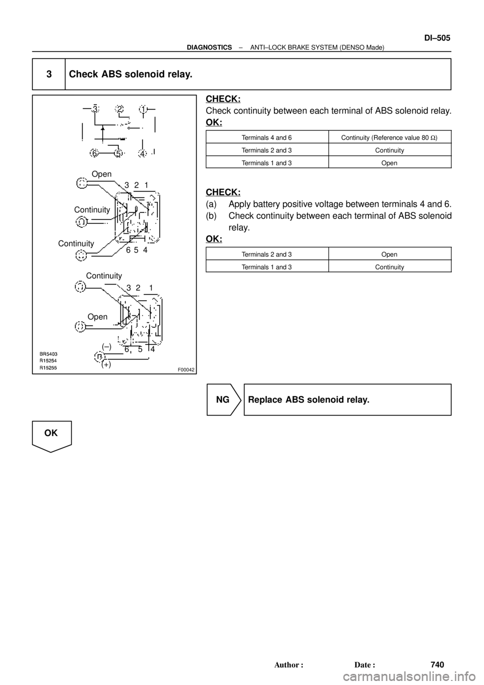
3 Check ABS solenoid relay.
CHECK:
Check continuity between each terminal of ABS solenoid relay.
OK:
Terminals 4 and 6Continuity (Reference value 80 W)
Terminals 2 and 3Continuity
Terminals 1 and 3Open
CHECK:
(a) Apply battery positive voltage between terminals 4 and 6.
(b) Check continuity between each terminal of ABS solenoid
relay.
OK:
Terminals 2 and 3Open
Terminals 1 and 3Continuity
NG Replace ABS solenoid relay.
OK