Page 1173 of 4592

S05390
No.1 Cooling
Fan Relay
CO06V±03
B02801
Ohmmeter
ContinuityOhmmeter
Continuity4 1
3
2
B02802
No ContinuityOhmmeter
4 1
3
2Battery
S05387
No.2 Cooling
Fan Relay
S04972
Ohmmeter
1
32 4
No Continuity Continuity
5
Continuity OhmmeterOhmmeter
± COOLING (5S±FE)COOLING FAN RELAY
CO±33
1607 Author�: Date�:
COOLING FAN RELAY
INSPECTION
1. INSPECT NO.1 COOLING FAN RELAY
(a) Remove the relay box cover.
(b) Remove the No.1 cooling fan relay. (Marking: FAN NO.1)
(c) Inspect the No.1 cooling fan relay continuity.
(1) Using an ohmmeter, check that there is continuity
between terminals 1 and 2.
If there is no continuity, replace the relay.
(2) Check that there is continuity between terminals 3
and 4.
If there is no continuity, replace the relay.
(d) Inspect the No.1 cooling fan relay operation.
(1) Apply battery positive voltage across terminals 1
and 2.
(2) Using an ohmmeter, check that there is no continu-
ity between terminals 3 and 4.
If there is continuity, replace the relay.
(e) Reinstall the No.1 cooling fan relay
(f) Reinstall the relay box cover.
2. INSPECT NO.2 COOLING FAN RELAY
(a) Remove the relay box cover.
(b) Remove the No.2 cooling fan relay. (Marking: FAN NO.2)
(c) Inspect the No.2 cooling fan relay continuity.
(1) Using an ohmmeter, check that there is continuity
between terminals 1 and 2.
If there is no continuity, replace the relay.
(2) Check that there is continuity between terminals 3
and 4.
If there is no continuity, replace the relay.
(3) Check that there is no continuity between terminals
3 and 5.
If there is continuity, replace the relay.
Page 1174 of 4592

S04971
Ohmmeter1
32 4
No Continuity Battery
Continuity 5Ohmmeter
S05388
No.3 Cooling
Fan Relay
S04970
Ohmmeter
1
32 Continuity
5Ohmmeter
No Continuity
S04969
Ohmmeter
1
32
Continuity 5
Battery CO±34
± COOLING (5S±FE)COOLING FAN RELAY
1608 Author�: Date�:
(d) Inspect the No.2 cooling fan relay operation.
(1) Apply battery positive voltage across terminals 1
and 2.
(2) Using an ohmmeter, check that there is no continu-
ity between terminals 3 and 4
If there is continuity, replace the relay.
(3) Check that there is continuity between terminals 3
and 5.
If there is no continuity, replace the relay.
(e) Reinstall the No.2 cooling fan relay.
(f) Reinstall the relay box cover.
3. INSPECT NO.3 COOLING FAN RELAY
(a) Remove the relay box cover.
(b) Remove the No.3 cooling fan relay. (Marking: FAN NO.3)
(c) Inspect the No.3 cooling fan relay continuity.
(1) Using an ohmmeter, check that there is continuity
between terminals 1 and 2.
If there is no continuity, replace the relay.
(2) Check that there is no continuity between terminals
3 and 5.
If there is continuity, replace the relay.
(d) Inspect the No.3 cooling fan relay operation.
(1) Apply battery positive voltage across terminals 1
and 2.
(2) Using an ohmmeter, check that there is continuity
between terminals 3 and 5.
If there is no continuity, replace the relay.
(e) Reinstall the No.3 cooling fan relay.
(f) Reinstall the relay box cover.
Page 1190 of 4592
CO03N±03
B06399
Radiator
No.1 ECT Switch
No.2 Cooling Fan Connector
Upper Radiator Support Upper Radiator Hose
No.1 Cooling Fan Connector
No.1 ECT Switch Wire Connector Radiator Assembly
Lower Radiator
Support� O±Ring
A/T Oil Cooler Hose
Relay Block
(for Daytime Running Light System) No.1 ECT Switch Wire No.1 Cooling FanNo.2 Cooling Fan
Upper Radiator Support
Lower Radiator
Support
� Non±reusable part� O±Ring Drain PlugLower
Radiator
Hose A/T Oil Cooler Hose
Lower Radiator Hose CO±16
± COOLING (1MZ±FE)RADIATOR
1624 Author�: Date�:
COMPONENTS
Page 1192 of 4592
RADIATOR
1626 Author�: Date�:
REMOVAL
HINT:
�At the time of installation, please refer to the following
items.
�Start the")
CO03O±03
S04725
B05937
Lower
Hose
Oil
Cooler
Hose
CO±18
± COOLING (1MZ±FE)RADIATOR
1626 Author�: Date�:
REMOVAL
HINT:
�At the time of installation, please refer to the following
items.
�Start the engine, and check for coolant and A/T fluid
leaks.
�Check the A/T fluid level. (See page DI±438)
1. DRAIN ENGINE COOLANT
2. CANADA:
DISCONNECT RELAY BLOCK (FOR DAYTIME
RUNNING LIGHT SYSTEM) FROM BATTERY
HOLD±DOWN CLAMP
3. DISCONNECT UPPER RADIATOR HOSE FROM
RADIATOR
4. DISCONNECT LOWER RADIATOR HOSE FROM
WATER INLET PIPE
5. DISCONNECT A/T OIL COOLER HOSES FROM OIL
COOLER PIPES
6. DISCONNECT NO.1 AND NO.2 COOLING FAN
CONNECTORS
7. DISCONNECT NO.1 ECT SWITCH WIRE CONNECTOR
8. REMOVE RADIATOR AND COOLING FANS
ASSEMBLY
(a) Remove the 2 bolts and 2 upper supports.
Torque: 12.8 N´m (130 kgf´cm, 9 ft´lbf)
(b) Lift out the radiator, and remove the radiator and cooling
fans assembly.
(c) Remove the 2 lower supports.
9. REMOVE A/T OIL COOLER HOSES FROM
RADIATOR
10. REMOVE LOWER RADIATOR HOSE FROM
RADIATOR
Page 1199 of 4592
ELECTRIC COOLING FAN
CO±25
1633 Author�: Date�:
ELECTRIC COOLING FAN
ON±VEHICLE INSPECTION
1. CHECK COOLING FAN O")
B05939
CO03S±03
S04727
Disconnect
B05940
B05941
Ammeter
Battery
± COOLING (1MZ±FE)ELECTRIC COOLING FAN
CO±25
1633 Author�: Date�:
ELECTRIC COOLING FAN
ON±VEHICLE INSPECTION
1. CHECK COOLING FAN OPERATION WITH LOW
TEMPERATURE (Below 88°C (190°F))
(a) Turn the ignition switch ON.
(b) Check that the cooling fan stops.
If not, check the cooling fan relay and ECT switch, and check
for a separated connector or severed wire between the cooling
fan relay and ECT switch.
(c) Disconnect the No.1 ECT switch connector.
(d) Check that the cooling fan rotates.
If not, check the fuses, engine main relay, cooling fan relay,
cooling fan, and check for a short circuit between the cooling
fan relay and ECT switch.
(e) Reconnect the No.1 ECT switch connector.
2. CHECK COOLING FAN OPERATION WITH HIGH
TEMPERATURE (Above 98°C (208°F))
(a) Start the engine, and raise coolant temperature to above
98°C (208°F).
(b) Check that the cooling fan rotates.
If not, replace the No.1 ECT switch.
3. INSPECT NO.1 COOLING FAN
(a) Disconnect the cooling fan connector.
(b) Connect battery and ammeter to the cooling fan connec-
tor.
(c) Check that the cooling fan rotates smoothly, and check
the reading on the ammeter.
Standard amperage: 8.3 ± 11.3 A at 20°C (68°F)
(d) Reconnect the cooling fan connector.
Page 1201 of 4592
CO03T±03
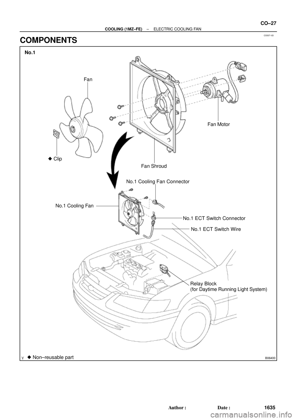
B06400
No.1 Cooling FanNo.1 Cooling Fan Connector
No.1 ECT Switch Connector
No.1 ECT Switch Wire
Relay Block
(for Daytime Running Light System)
� Non±reusable part� ClipFan
Fan ShroudFan Motor
No.1
± COOLING (1MZ±FE)ELECTRIC COOLING FAN
CO±27
1635 Author�: Date�:
COMPONENTS
Page 1203 of 4592
CO03U±03
B05943
B05944
± COOLING (1MZ±FE)ELECTRIC COOLING FAN
CO±29
1637 Author�: Date�:
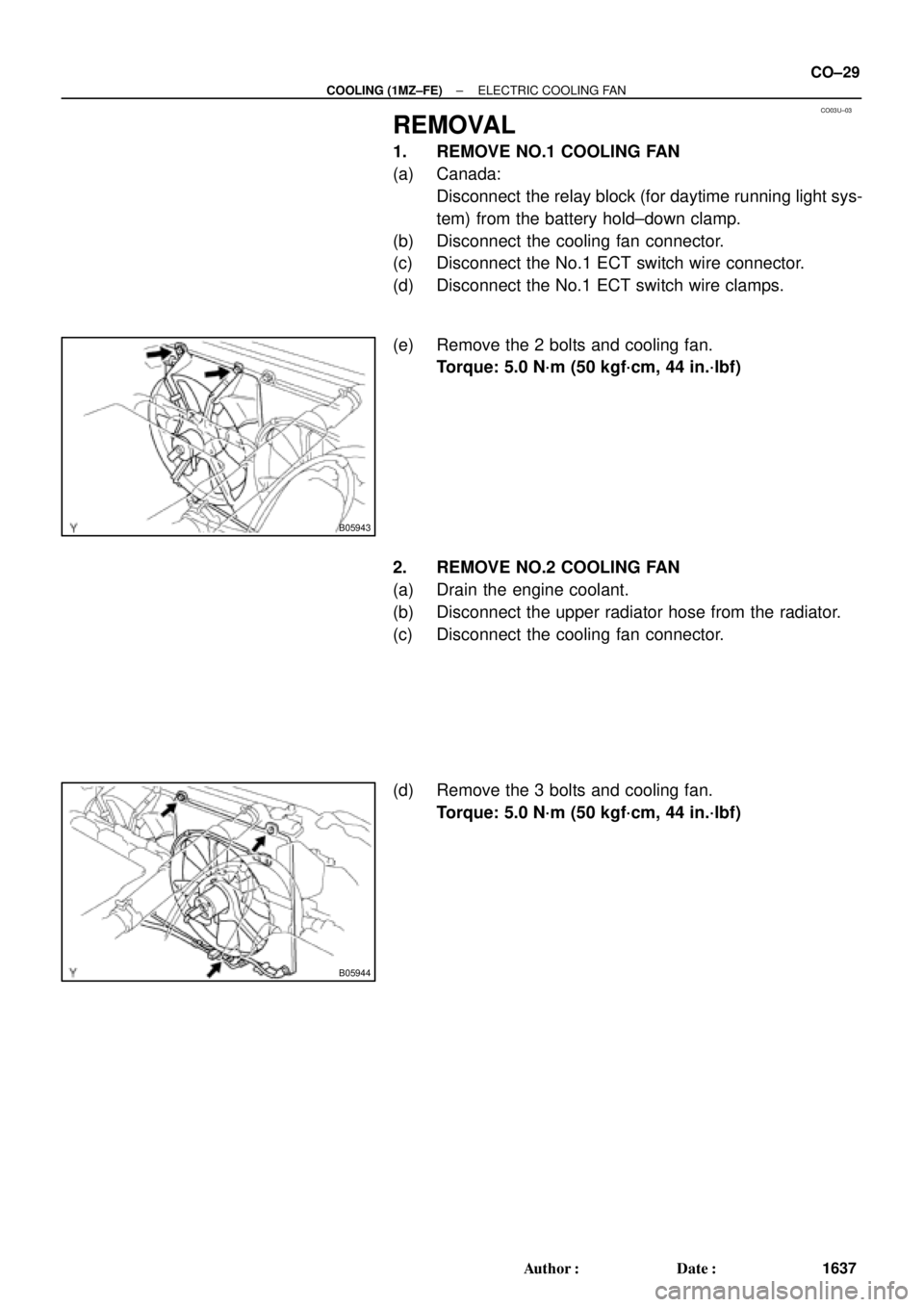
REMOVAL
1. REMOVE NO.1 COOLING FAN
(a) Canada:
Disconnect the relay block (for daytime running light sys-
tem) from the battery hold±down clamp.
(b) Disconnect the cooling fan connector.
(c) Disconnect the No.1 ECT switch wire connector.
(d) Disconnect the No.1 ECT switch wire clamps.
(e) Remove the 2 bolts and cooling fan.
Torque: 5.0 N´m (50 kgf´cm, 44 in.´lbf)
2. REMOVE NO.2 COOLING FAN
(a) Drain the engine coolant.
(b) Disconnect the upper radiator hose from the radiator.
(c) Disconnect the cooling fan connector.
(d) Remove the 3 bolts and cooling fan.
Torque: 5.0 N´m (50 kgf´cm, 44 in.´lbf)
Page 1210 of 4592

S05391
Engine
Main Relay
CO03Z±03
S04974
Ohmmeter
1
Continuity OhmmeterOhmmeter Continuity
No
Continuity 2
5
43
S04973
Ohmmeter
1
Ohmmeter
Continuity No
Continuity
2
5
43
Battery CO±36
± COOLING (1MZ±FE)ENGINE MAIN RELAY
1644 Author�: Date�:
ENGINE MAIN RELAY
INSPECTION
1. REMOVE RELAY BOX COVER
2. REMOVE ENGINE MAIN RELAY
(Marking: ENGINE MAIN)
3. INSPECT RELAY CONTINUITY
(a) Using an ohmmeter, check that there is continuity be-
tween terminals 3 and 5.
If there is no continuity, replace the relay.
(b) Check that there is continuity between terminals 2 and 4.
If there is no continuity, replace the relay.
(c) Check that there is no continuity between terminals 1 and
2.
If there is continuity, replace the relay.
4. INSPECT RELAY OPERATION
(a) Apply battery positive voltage across terminals 3 and 5.
(b) Using an ohmmeter, check that there is no continuity be-
tween terminals 2 and 4.
If there is continuity, replace the relay.
(c) Check that there is continuity between terminals 1 and 2.
If there is no continuity, replace the relay.
5. REINSTALL ENGINE MAIN RELAY
6. REINSTALL RELAY BOX COVER