Page 725 of 4592

± BODY ELECTRICALBODY ELECTRICAL SYSTEM
BE±9
2229 Author�: Date�:
ºWindow Lock Illuminationº does not light up.1. Power Window Master SwitchBE±60
Key±off power window does not operate.
1. GAUGE Fuse (I/P J/B No.1)
2. Integration Relay (I/P J/B No.1)
3. Ignition Switch
4. Door Courtesy Switch
5. Wire Harness±
BE±60
BE±14
BE±32
±
POWER DOOR LOCK CONTROL SYSTEM
SymptomSuspect AreaSee page
ºDoor lock systemº does not operate at all.
1. POWER M±Fuse (I/P J/B No.1)
2. CIG Fuse (I/P J/B No.1)
3. DOOR Fuse (I/P J/B No.1)
4. Integration Relay (I/P J/B No.1)
5. Wire Harness±
±
±
BE±70
±
Door lock system does not operate by manual switch.
1. Power Window Master Switch
2. Door Lock Manual Switch
3. Integration Relay (I/P J/B No.1)
4. Wire HarnessBE±60
BE±70
BE±70
±
Door lock system does not operate by door key.
1. Door Key Lock and Unlock Switch
2. Integration Relay (I/P J/B No.1)
3. Wire Harness
4. Door Lock Link DisconnectedBE±70
BE±70
±
±
Fault in 2±Operation unlock function of Driver's side door key lock
and unlock switch.1. Door Key Lock and Unlock Switch
2. Integration Relay (I/P J/B No.1)
3. Wire HarnessBE±70
BE±70
±
Fault in key confine prevention operate.
1. Integration Relay (I/P J/B No.1)
2. Key Unlock Warning Switch
3. Door Courtesy Switch
4. Wire HarnessBE±70
BE±14
BE±32
±
Only one door lock does not operate.1. Door Lock Motor
2. Wire HarnessBE±70
±
SLIDING ROOF SYSTEM
SymptomSuspect AreaSee page
Sliding roof system does not operate.
(Door Lock does not operate)1. POWER M±Fuse (I/P J/B No.1)
2. Power Main Relay (I/P J/B No.1)
3. Wire Harness±
BE±60
±
Sliding roof system does not operate.
(Door Lock is normal)
1. Ignition Switch
2. Sliding Roof Control Relay and Switch
3. Sliding Roof Motor and Limit Switch
4. Wire HarnessBE±14
BE±74
BE±74
±
Sliding roof system operates abnormally.
1. Sliding Roof Control Relay and Switch
2. Sliding Roof Motor and Limit Switch
3. Wire HarnessBE±74
BE±74
±
Sliding roof system stops operation half way.
(Stones of foreign material trapped in motor assembly)1. Sliding Roof Control Relay and Switch
2. Sliding Roof Motor and Limit Switch
3. Wire HarnessBE±74
BE±74
±
ºKey±off Sliding Roofº operation does not operate.
1. DOME Fuse (E/G Room J/B No.2)
2. GAUGE Fuse (I/P J/B No.1)
3. Ignition Switch
4. Integration Relay (I/P J/B No.1)
5. Wire Harness±
±
BE±14
BE±14
±
Page 727 of 4592
BE0A0±03
Z19043
Engine Room Relay Block No.1
Engine Room Junction
Block No.2
Engine Room Relay Block No.2
Instrument Panel Junction Block No.1
Turn Signal Flasher
± BODY ELECTRICALPOWER SOURCE
BE±11
2231 Author�: Date�:
POWER SOURCE
LOCATION
Page 729 of 4592
BE0A2±03
N20687
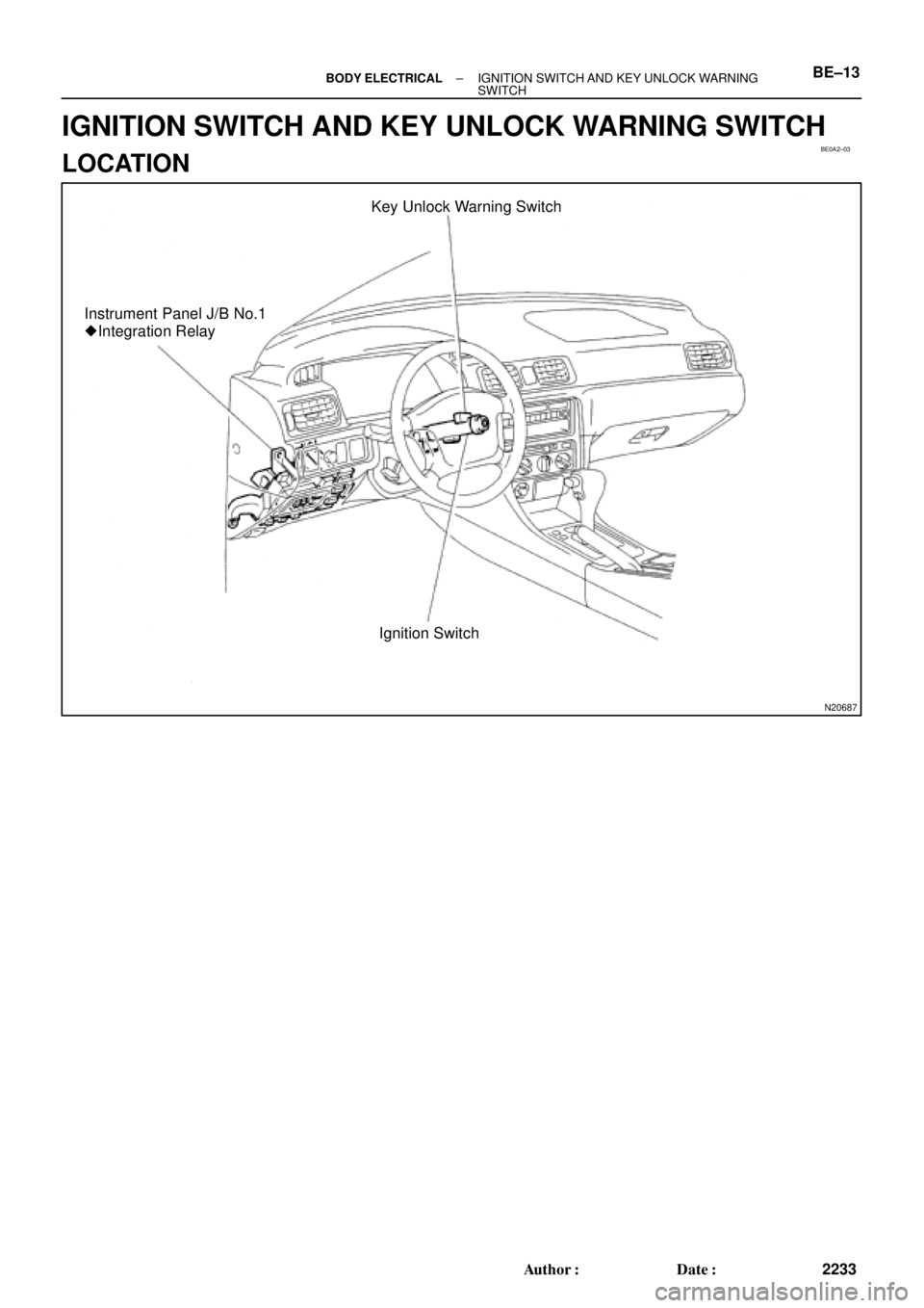
Key Unlock Warning Switch
Instrument Panel J/B No.1
� Integration Relay
Ignition Switch
± BODY ELECTRICALIGNITION SWITCH AND KEY UNLOCK WARNING
SWITCHBE±13
2233 Author�: Date�:
IGNITION SWITCH AND KEY UNLOCK WARNING SWITCH
LOCATION
Page 730 of 4592

BE0A3±02
N14824
LOCKACC
ON
1 3 4
5 76 8
START2
N20125
OFF
ON
1
2
N20126
101
6
5
N20127
101
6
5 BE±14
± BODY ELECTRICALIGNITION SWITCH AND KEY UNLOCK WARNING
SWITCH
2234 Author�: Date�:
INSPECTION
1. INSPECT IGNITION SWITCH CONTINUITY
Switch positionTester connectionSpecified condition
LOCK±No continuity
ACC2 ± 3Continuity
ON2 ± 3 ± 4
6 ± 7Continuity
START1 ± 2 ± 4
6 ± 7 ± 8Continuity
If continuity is not as specified, replace the switch.
2. INSPECT KEY UNLOCK WARNING SWITCH CONTI-
NUITY
Switch positionTester connectionSpecified condition
OFF (Key removed)±No continuity
ON (Key set)1 ± 2Continuity
If continuity is not as specified, replace the switch.
3. Key unlock warning system:
INSPECT INTEGRATION RELAY (TYPE A) OPERA-
TION
(a) Connect the positive (+) lead from the battery to terminal
1.
(b) Connect the negative (±) lead from the battery to termi-
nals 5, 6 and 10.
(c) Check the buzzer sounds.
(d) Disconnect the negative (±) lead from the battery to termi-
nal 6.
(e) Check that the buzzerr stops sounding.
Page 731 of 4592
 Connect the negative (±) lea")
N20128
101
6
5
N20129
10
1 6
5
N20130
101 65
N20131
101 65
N20132
101 6
5
± BODY ELECTRICALIGNITION SWITCH AND KEY UNLOCK WARNING
SWITCHBE±15
2235 Author�: Date�:
(f) Connect the negative (±) lead from the battery to terminal
6.
(g) Disconnect the negative (±) lead from the battery to termi-
nal 5.
(h) Check that the buzzerr stops sounding.
If operation is not as specified, replace the relay.
4. Key unlock warning system:
INSPECT INTEGRATION RELAY (TYPE B) OPERA-
TION
(a) Connect the positive (+) lead from the battery to terminal
1.
(b) Connect the negative (±) lead from the battery to termi-
nals 5, 6 and 10.
(c) Check the buzzerr sounds.
(d) Disconnect the negative (±) lead from the battery to termi-
nal 6.
(e) Check that the buzzerr stops sounding.
(f) Connect the negative (±) lead from the battery to terminal
6.
(g) Disconnect the negative (±) lead from the battery to termi-
nal 5.
(h) Check that the buzzerr stops sounding.
If operation is not as specified, replace the relay.
5. Key unlock warning system:
INSPECT INTEGRATION RELAY (TYPE C) OPERA-
TION
(a) Connect the positive (+) lead from the battery to terminal
1.
(b) Connect the negative (±) lead from the battery to termi-
nals 5, 6 and 10.
(c) Check the buzzerr sounds.
Page 732 of 4592
 Disconnect the negat")
N20133
101 65
N20134
101 65
N20135
Junction block side:
1 2 3 4 5 6 7 8 10 11 9 12
BE±16± BODY ELECTRICALIGNITION SWITCH AND KEY UNLOCK WARNING
SWITCH
2236 Author�: Date�:
(d) Disconnect the negative (±) lead from the battery to termi-
nal 6.
(e) Check that the buzzerr stops sounding.
(f) Connect the negative (±) lead from the battery to terminal
6.
(g) Disconnect the negative (±) lead from the battery to termi-
nal 5.
(h) Check that the buzzerr stops sounding.
If operation is not as specified, replace the relay.
6. INSPECT INTEGRATION RELAY (TYPE A) CIRCUIT
(a) Remove the relay from the junction block No.1 and in-
spect the connector on the junction block side.
Tester connectionConditionSpecified condition
2 ± Ground
4 ± GroundPassenger's door courtesy switch OFF (Door
closed)No continuity
2 ± Ground
4 ± GroundPassenger's door courtesy switch ON (Door
opened)Continuity
5 ± GroundKey unlock warning switch OFFNo continuity
5 ± GroundKey unlock warning switch ONContinuity
6 ± GroundDriver's door courtesy switch OFFNo continuity
6 ± GroundDriver's door courtesy switch ONContinuity
8 ± GroundBuckle switch OFF (Seat belt unfastened)No continuity
8 ± GroundBuckle switch ON (Seat belt fastened)Continuity
10 ± GroundConstantContinuity
1 ± GroundConstantBattery positive voltage
7 ± Ground
9 ± GroundIgnition switch LOCK or ACCNo voltage
7 ± Ground
9 ± GroundIgnition switch ONBattery positive voltage
Page 733 of 4592
 Disconnect the co")
N20136
Wire harness side:
1234
N20135
Junction block side:
1 2 3 4 5 6 7 8
10 119
12
± BODY ELECTRICALIGNITION SWITCH AND KEY UNLOCK WARNING
SWITCHBE±17
2237 Author�: Date�:
(b) Disconnect the connector from the integration relay and
inspect the connector on the wire harness side.
Tester connectionConditionSpecified condition
1 ± GroundLight control switch OFFNo continuity
1 ± GroundLight control switch HEAD or TAILContinuity
4 ± GroundLight control switch OFF or TAILNo continuity
4 ± GroundLight control switch HEADContinuity
2 ± Ground
3 ± GroundConstantBattery positive voltage
If the circuit is as specified, try replacing the relay with a new
one.
If the circuit is not as specified, inspect the circuits connected
to other parts.
7. INSPECT INTEGRATION RELAY (TYPE B) CIRCUIT
(a) Remove the relay from the junction block No.1 and in-
spect the connector on the junction block side.
Tester connectionConditionSpecified condition
2 ± GroundAll door courtesy switches OFF (Except Driver's
Door/ Door closed)No continuity
2 ± GroundOne of the door courtesy switches ON (Except
Driver's Door/ Door opened)Continuity
4 ± GroundDoor courtesy switches except that of the driver's
door OFF (Door closed)No continuity
4 ± GroundOne of the door courtesy switches except that of
the driver's door ON (Door opened)Continuity
Page 734 of 4592

N20137
Wire harness side:
Wire harness side:
20 14 13 1211 10 8 479
22 21 19 18 17 15 1656 123
23 24 25
1234
Connector ºAº
Connector ºBº
eh±25±1
h±4±1
BE±18± BODY ELECTRICALIGNITION SWITCH AND KEY UNLOCK WARNING
SWITCH
2238 Author�: Date�:
5 ± GroundKey unlock warning switch OFFNo continuity
5 ± GroundKey unlock warning switch ONContinuity
6 ± GroundDriver's door courtesy switch OFF (Door closed)No continuity
6 ± GroundDriver's door courtesy switch ON (Door opened)Continuity
8 ± GroundBuckle switch OFF (Seat belt unfastened)No continuity
8 ± GroundBuckle switch ON (Seat belt fastened)Continuity
10 ± GroundConstantContinuity
1 ± GroundConstantBattery positive voltage
7 ± Ground
9 ± GroundIgnition switch LOCK or ACCNo voltage
7 ± Ground
9 ± GroundIgnition switch ONBattery positive voltage
11 ± GroundIgnition switch LOCKNo voltage
11 ± GroundIgnition switch ACC or ONBattery positive voltage
(b) Disconnect the connector from the integration relay and
inspect the connectors on the wire harness side.
Tester connectionConditionSpecified condition
A3 ± GroundConstantContinuity
A5 ± GroundDriver's door unlock detection switch OFF (Door
locked)No continuity
A5 ± GroundDriver's door unlock detection switch ON (Door
unlocked)Continuity
A6 ± GroundPassenger's door courtesy switch OFF (Door
closed)No continuity