Page 1211 of 2543
LUBRICATION SYSTEM
PREPARATION
SST (SPECIAL SERVICE TOOLS)
09032±00100 Oil Pan Seal Cutter
09228±07500 Oil Filter Wrench
09316±60010 Transmission & Transfer Bearing
Replacer
(09316±00010) Replacer Pipe
09816±30010 Oil Pressure Switch Socket
No.2 oil pan
Crankshaft front oil seal
RECOMMENDED TOOLS
09040±00010 Hexagon Wrench Set
09040±00020 Torx Socket E10
09200±00010Engine Adjust Kit
A/C compressor stud bolt
EQUIPMENT
������������������������� �
������������������������ �������������������������Oil pressure gauge����������� �
���������� �����������
������������������������� �
������������������������ �������������������������Precision straight edge����������� �
���������� ����������� Oil pump
������������������������� �
������������������������ �������������������������Torque wrench����������� �
���������� �����������
± ENGINELUBRICATION SYSTEMEG±359
Page 1214 of 2543
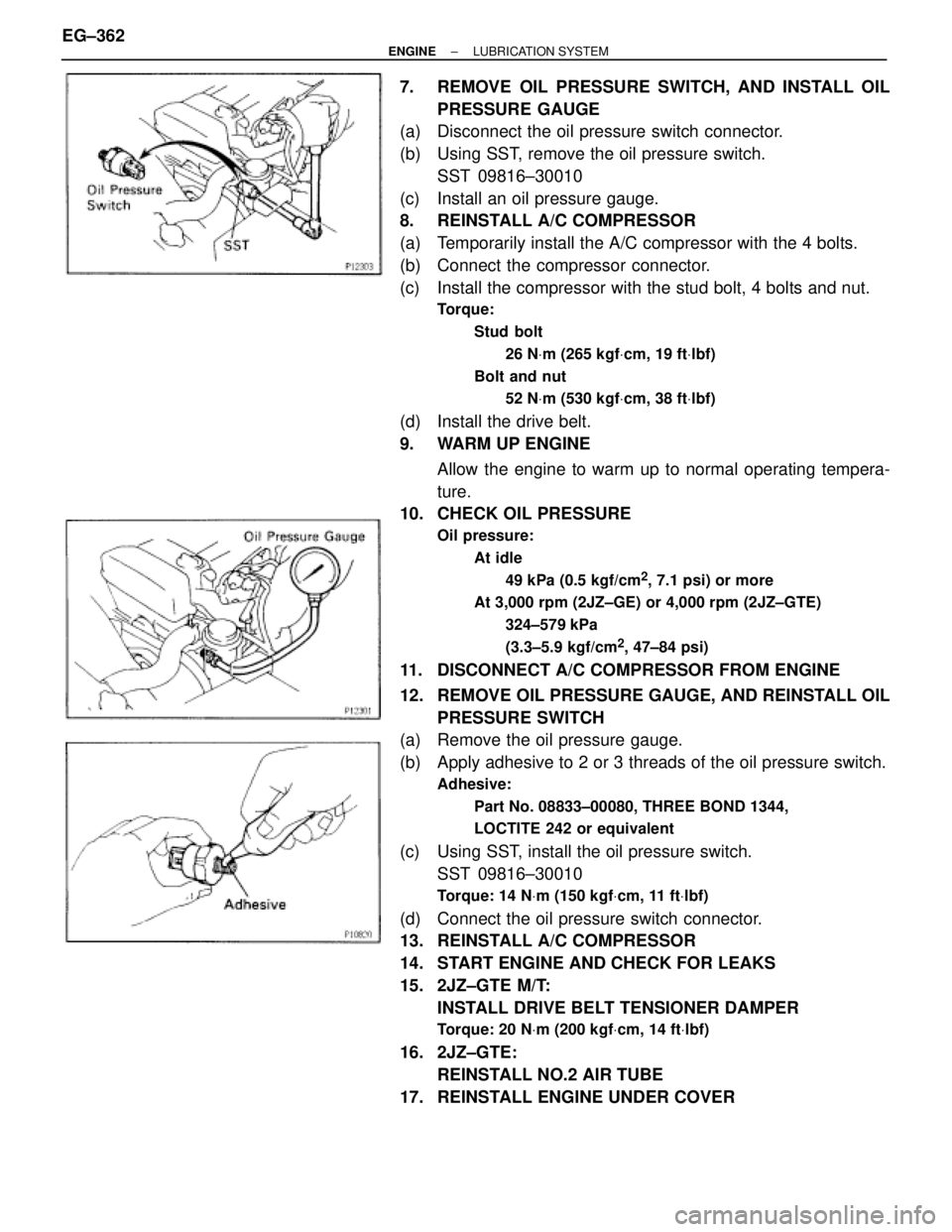
7. REMOVE OIL PRESSURE SWITCH, AND INSTALL OIL
PRESSURE GAUGE
(a) Disconnect the oil pressure switch connector.
(b) Using SST, remove the oil pressure switch.
SST 09816±30010
(c) Install an oil pressure gauge.
8. REINSTALL A/C COMPRESSOR
(a) Temporarily install the A/C compressor with the 4 bolts.
(b) Connect the compressor connector.
(c) Install the compressor with the stud bolt, 4 bolts and nut.
Torque:
Stud bolt
26 NVm (265 kgfVcm, 19 ftVlbf)
Bolt and nut
52 NVm (530 kgfVcm, 38 ftVlbf)
(d) Install the drive belt.
9. WARM UP ENGINE
Allow the engine to warm up to normal operating tempera-
ture.
10. CHECK OIL PRESSURE
Oil pressure:
At idle
49 kPa (0.5 kgf/cm
2, 7.1 psi) or more
At 3,000 rpm (2JZ±GE) or 4,000 rpm (2JZ±GTE)
324±579 kPa
(3.3±5.9 kgf/cm
2, 47±84 psi)
11. DISCONNECT A/C COMPRESSOR FROM ENGINE
12. REMOVE OIL PRESSURE GAUGE, AND REINSTALL OIL
PRESSURE SWITCH
(a) Remove the oil pressure gauge.
(b) Apply adhesive to 2 or 3 threads of the oil pressure switch.
Adhesive:
Part No. 08833±00080, THREE BOND 1344,
LOCTITE 242 or equivalent
(c) Using SST, install the oil pressure switch.
SST 09816±30010
Torque: 14 NVm (150 kgfVcm, 11 ftVlbf)
(d) Connect the oil pressure switch connector.
13. REINSTALL A/C COMPRESSOR
14. START ENGINE AND CHECK FOR LEAKS
15. 2JZ±GTE M/T:
INSTALL DRIVE BELT TENSIONER DAMPER
Torque: 20 NVm (200 kgfVcm, 14 ftVlbf)
16. 2JZ±GTE:
REINSTALL NO.2 AIR TUBE
17. REINSTALL ENGINE UNDER COVER EG±362
± ENGINELUBRICATION SYSTEM
Page 1216 of 2543
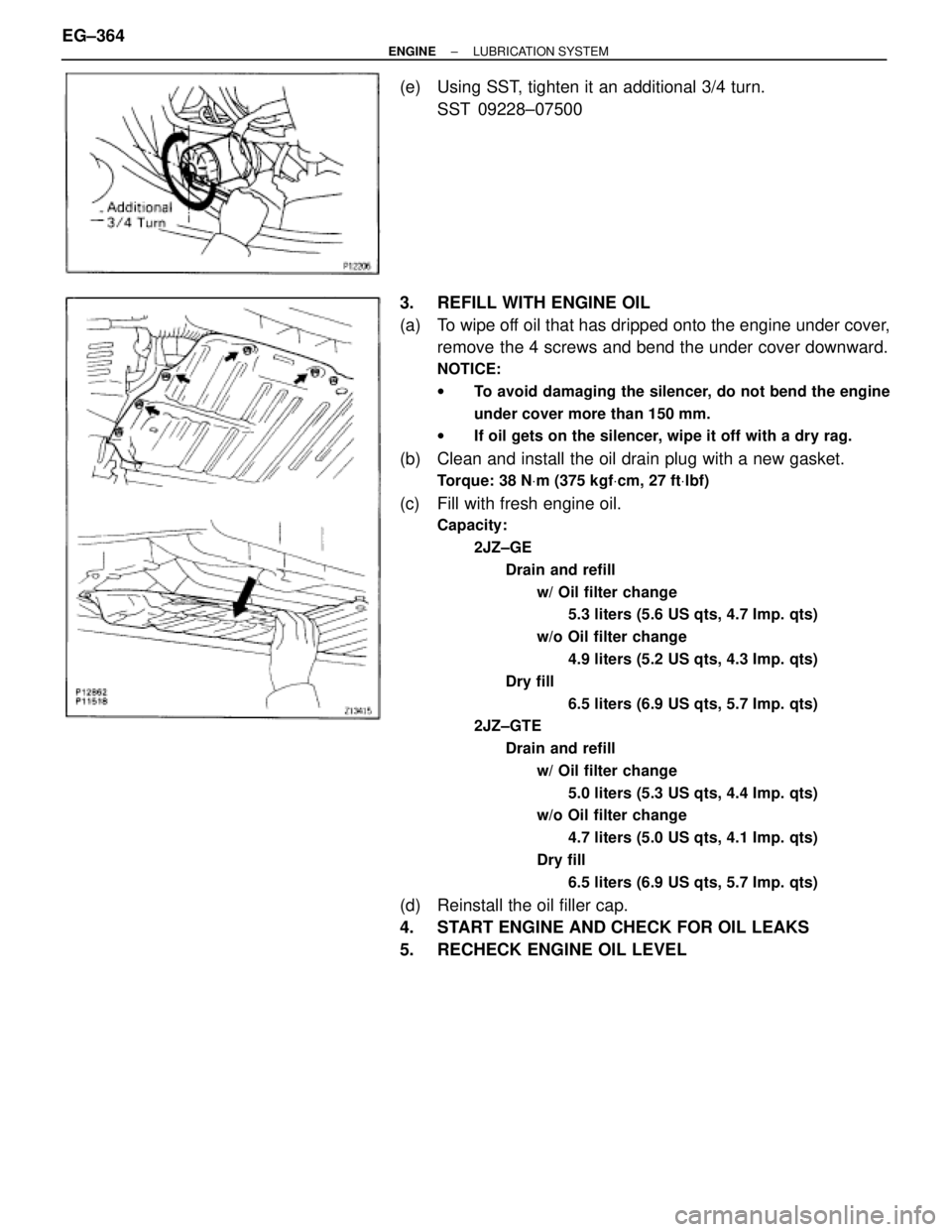
(e) Using SST, tighten it an additional 3/4 turn.
SST 09228±07500
3. REFILL WITH ENGINE OIL
(a) To wipe off oil that has dripped onto the engine under cover,
remove the 4 screws and bend the under cover downward.
NOTICE:
wTo avoid damaging the silencer, do not bend the engine
under cover more than 150 mm.
wIf oil gets on the silencer, wipe it off with a dry rag.
(b) Clean and install the oil drain plug with a new gasket.
Torque: 38 NVm (375 kgfVcm, 27 ftVlbf)
(c) Fill with fresh engine oil.
Capacity:
2JZ±GE
Drain and refill
w/ Oil filter change
5.3 liters (5.6 US qts, 4.7 Imp. qts)
w/o Oil filter change
4.9 liters (5.2 US qts, 4.3 Imp. qts)
Dry fill
6.5 liters (6.9 US qts, 5.7 Imp. qts)
2JZ±GTE
Drain and refill
w/ Oil filter change
5.0 liters (5.3 US qts, 4.4 Imp. qts)
w/o Oil filter change
4.7 liters (5.0 US qts, 4.1 Imp. qts)
Dry fill
6.5 liters (6.9 US qts, 5.7 Imp. qts)
(d) Reinstall the oil filler cap.
4. START ENGINE AND CHECK FOR OIL LEAKS
5. RECHECK ENGINE OIL LEVEL EG±364
± ENGINELUBRICATION SYSTEM
Page 1223 of 2543
INSTALLATION HINT:
Use a new gasket (2JZ±GE) or O±ring (2JZ±GTE).
Torque:
2JZ±GE
49 NVm (500 kgfVcm, 36 ftVlbf)
2JZ±GTE
29 NVm (300 kgfVcm, 22 ftVlbf)
2. REMOVE DRIVE AND DRIVEN ROTORS
Remove the 10 screws, pump body cover, the drive and driv-
en rotors.
Torque: 10 NVm (105 kgfVcm, 8.0 ftVlbf)
ASSEMBLY HINT: Place the drive and driven rotors into the
oil pump body with the mark facing upward.
OIL PUMP INSPECTION
1. INSPECT RELIEF VALVE
Coat the valve with engine oil and check that it falls smoothly
into the valve hole under its own weight.
If it doesn't, replace the relief valve. If necessary, replace the
oil pump assembly.
2. INSPECT DRIVE AND DRIVEN ROTORS
A. Place drive and driven rotors into oil pump body
ASSEMBLY HINT: Place the drive and driven rotors into the
oil pump body with the mark facing upward.
± ENGINELUBRICATION SYSTEMEG±371
Page 1225 of 2543
Maximum side clearance:
2JZ±GE
0.12 mm (0.0047 in.)
2JZ±GTE
0.10 mm (0.0039 in.)
If the side clearance is greater than maximum, replace the ro-
tors as a set. If necessary, replace the oil pump assembly.
E. Remove drive and driven rotors
OIL PUMP INSTALLATION
1. INSTALL OIL PUMP
(a) Remove any old packing (FIPG) material and be careful not
to drop any oil on the contact surfaces of the oil pump and
cylinder block.
wUsing a razor blade gasket scraper, remove all the old
packing (FIPG) material from the gasket surfaces and
sealing groove.
wThoroughly clean all components to remove all the
debris.
wUsing a non±residue solvent, clean both sealing
surfaces.
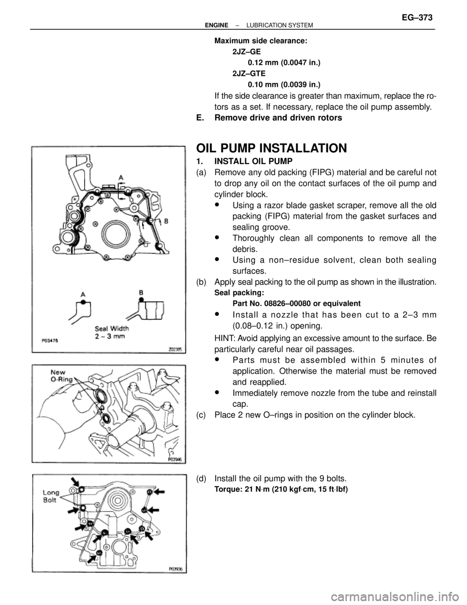
(b) Apply seal packing to the oil pump as shown in the illustration.
Seal packing:
Part No. 08826±00080 or equivalent
wInstall a nozzle that has been cut to a 2±3 mm
(0.08±0.12 in.) opening.
HINT: Avoid applying an excessive amount to the surface. Be
particularly careful near oil passages.
wParts must be assembled within 5 minutes of
application. Otherwise the material must be removed
and reapplied.
wImmediately remove nozzle from the tube and reinstall
cap.
(c) Place 2 new O±rings in position on the cylinder block.
(d) Install the oil pump with the 9 bolts.
Torque: 21 NVm (210 kgfVcm, 15 ftVlbf)
± ENGINELUBRICATION SYSTEMEG±373
Page 1226 of 2543
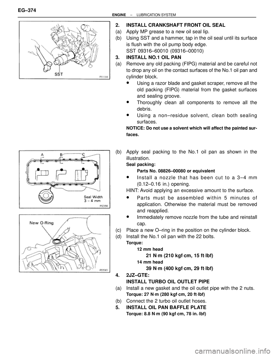
2. INSTALL CRANKSHAFT FRONT OIL SEAL
(a) Apply MP grease to a new oil seal lip.
(b) Using SST and a hammer, tap in the oil seal until its surface
is flush with the oil pump body edge.
SST 09316±60010 (09316±00010)
3. INSTALL NO.1 OIL PAN
(a) Remove any old packing (FIPG) material and be careful not
to drop any oil on the contact surfaces of the No.1 oil pan and
cylinder block.
wUsing a razor blade and gasket scraper, remove all the
old packing (FIPG) material from the gasket surfaces
and sealing groove.
wThoroughly clean all components to remove all the
debris.
wUsing a non±residue solvent, clean both sealing
surfaces.
NOTICE: Do not use a solvent which will affect the painted sur-
faces.
(b) Apply seal packing to the No.1 oil pan as shown in the
illustration.
Seal packing:
Parts No. 08826±00080 or equivalent
wInstall a nozzle that has been cut to a 3±4 mm
(0.12±0.16 in.) opening.
HINT: Avoid applying an excessive amount to the surface.
wParts must be assembled within 5 minutes of
application. Otherwise the material must be removed
and reapplied.
wImmediately remove nozzle from the tube and reinstall
cap.
(c) Place a new O±ring in the position on the cylinder block.
(d) Install the No.1 oil pan with the 22 bolts.
Torque:
12 mm head
21 NVm (210 kgfVcm, 15 ftVlbf)
14 mm head
39 NVm (400 kgfVcm, 29 ftVlbf)
4. 2JZ±GTE:
INSTALL TURBO OIL OUTLET PIPE
(a) Install a new gasket and the oil outlet pipe with the 2 nuts.
Torque: 27 NVm (280 kgfVcm, 20 ftVlbf)
(b) Connect the 2 turbo oil outlet hoses.
5. INSTALL OIL PAN BAFFLE PLATE
Torque: 8.8 NVm (90 kgfVcm, 78 in.Vlbf)
EG±374± ENGINELUBRICATION SYSTEM
Page 1227 of 2543
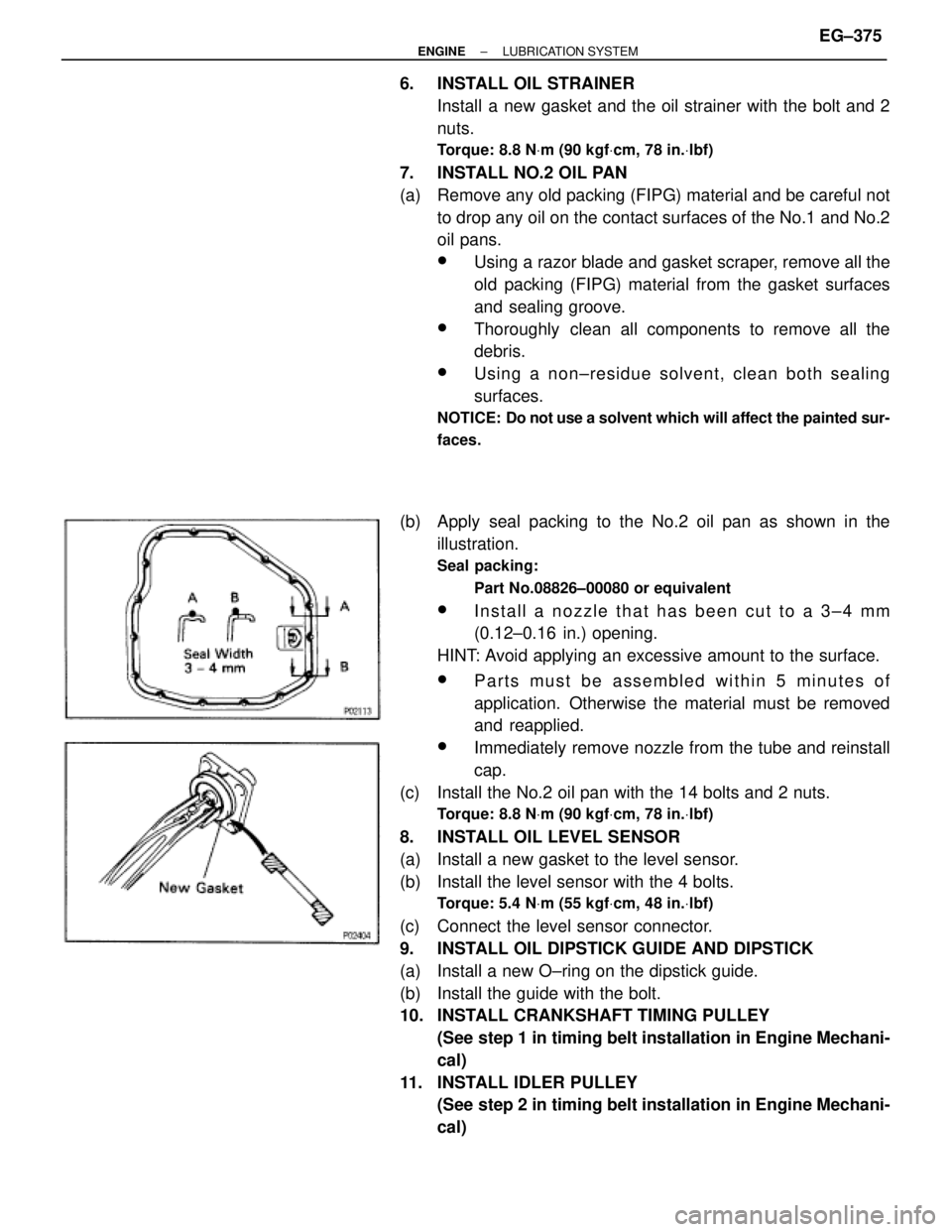
6. INSTALL OIL STRAINER
Install a new gasket and the oil strainer with the bolt and 2
nuts.
Torque: 8.8 NVm (90 kgfVcm, 78 in.Vlbf)
7. INSTALL NO.2 OIL PAN
(a) Remove any old packing (FIPG) material and be careful not
to drop any oil on the contact surfaces of the No.1 and No.2
oil pans.
wUsing a razor blade and gasket scraper, remove all the
old packing (FIPG) material from the gasket surfaces
and sealing groove.
wThoroughly clean all components to remove all the
debris.
wUsing a non±residue solvent, clean both sealing
surfaces.
NOTICE: Do not use a solvent which will affect the painted sur-
faces.
(b) Apply seal packing to the No.2 oil pan as shown in the
illustration.
Seal packing:
Part No.08826±00080 or equivalent
wInstall a nozzle that has been cut to a 3±4 mm
(0.12±0.16 in.) opening.
HINT: Avoid applying an excessive amount to the surface.
wParts must be assembled within 5 minutes of
application. Otherwise the material must be removed
and reapplied.
wImmediately remove nozzle from the tube and reinstall
cap.
(c) Install the No.2 oil pan with the 14 bolts and 2 nuts.
Torque: 8.8 NVm (90 kgfVcm, 78 in.Vlbf)
8. INSTALL OIL LEVEL SENSOR
(a) Install a new gasket to the level sensor.
(b) Install the level sensor with the 4 bolts.
Torque: 5.4 NVm (55 kgfVcm, 48 in.Vlbf)
(c) Connect the level sensor connector.
9. INSTALL OIL DIPSTICK GUIDE AND DIPSTICK
(a) Install a new O±ring on the dipstick guide.
(b) Install the guide with the bolt.
10. INSTALL CRANKSHAFT TIMING PULLEY
(See step 1 in timing belt installation in Engine Mechani-
cal)
11. INSTALL IDLER PULLEY
(See step 2 in timing belt installation in Engine Mechani-
cal)
± ENGINELUBRICATION SYSTEMEG±375
Page 1228 of 2543
12. 2JZ±GTE M/T:
INSTALL DRIVE BELT TENSIONER BRACKET
Torque: 27 NVm (280 kgfVcm, 20 ftVlbf)
13. INSTALL TIMING BELT
(See step 3 in timing belt installation in Engine Mechani-
cal)
14. 2JZ±GTE:
INSTALL CRANKSHAFT POSITION SENSOR
Torque: 8.8 NVm (90 kgfVcm, 78 in.Vlbf)
15. 2JZ±GTE:
INSTALL GENERATOR
16. REMOVE ENGINE STAND FROM ENGINE
17. ASSEMBLY ENGINE AND TRANSMISSION
(See components for engine removal & transmission
separation and assembly)
18. INSTALL ENGINE WITH TRANSMISSION
(See components for engine removal and installation)
OIL COOLER (2JZ±GTE)
COMPONENTS FOR REMOVAL AND
INSTALLATION
EG±376± ENGINELUBRICATION SYSTEM