Page 1701 of 2543

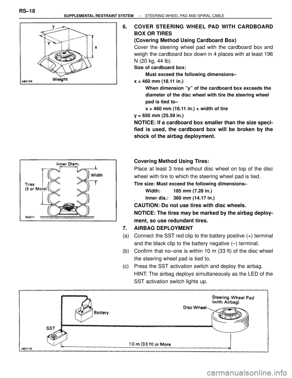
6. COVER STEERING WHEEL PAD WITH CARDBOARD
BOX OR TIRES
(Covering Method Using Cardboard Box)
Cover the steering wheel pad with the cardboard box and
weigh the cardboard box down in 4 places with at least 196
N (20 kg, 44 lb).
Size of cardboard box:
Must exceed the following dimensions±
x = 460 mm (18.11 in.)
When dimension ºyº of the cardboard box exceeds the
diameter of the disc wheel with tire the steering wheel
pad is tied to±
x = 460 mm (18.11 in.) + width of tire
y = 650 mm (25.59 in.)
NOTICE: If a cardboard box smaller than the size speci-
fied is used, the cardboard box will be broken by the
shock of the airbag deployment.
Covering Method Using Tires:
Place at least 3 tires without disc wheel on top of the disc
wheel with tire to which the steering wheel pad is tied.
Tire size: Must exceed the following dimensions±
Width: 185 mm (7.28 in.)
Inner dia.: 360 mm (14.17 in.)
CAUTION: Do not use tires with disc wheels.
NOTICE: The tires may be marked by the airbag deploy-
ment, so use redundant tires.
7. AIRBAG DEPLOYMENT
(a) Connect the SST red clip to the battery positive (+) terminal
and the black clip to the battery negative (±) terminal.
(b) Confirm that no±one is within 10 m (33 ft) of the disc wheel
the steering wheel pad is tied to.
(c) Press the SST activation switch and deploy the airbag.
HINT: The airbag deploys simultaneously as the LED of the
SST activation switch lights up. RS±18
± SUPPLEMENTAL RESTRAINT SYSTEMSTEERING WHEEL PAD AND SPIRAL CABLE
Page 1711 of 2543

CAUTION: If the front passenger airbag assembly is tied
down by too thin a wire harness, it may snap. This is
highly dangerous. Always use a wire harness which is at
least 1.25 mm
2 (0.0019 in.2).
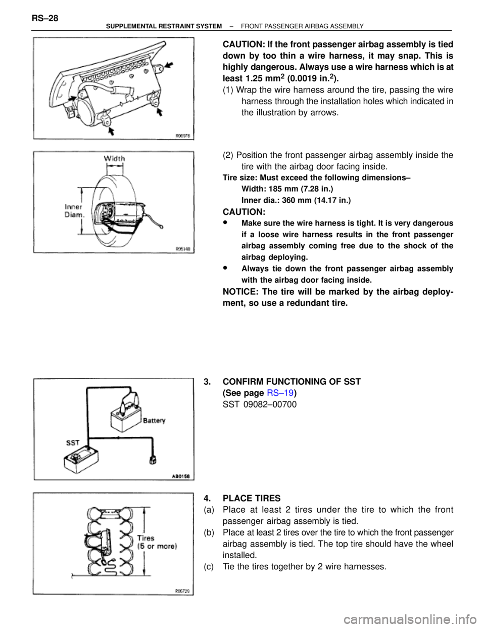
(1) Wrap the wire harness around the tire, passing the wire
harness through the installation holes which indicated in
the illustration by arrows.
(2) Position the front passenger airbag assembly inside the
tire with the airbag door facing inside.
Tire size: Must exceed the following dimensions±
Width: 185 mm (7.28 in.)
Inner dia.: 360 mm (14.17 in.)
CAUTION:
wMake sure the wire harness is tight. It is very dangerous
if a loose wire harness results in the front passenger
airbag assembly coming free due to the shock of the
airbag deploying.
wAlways tie down the front passenger airbag assembly
with the airbag door facing inside.
NOTICE: The tire will be marked by the airbag deploy-
ment, so use a redundant tire.
3. CONFIRM FUNCTIONING OF SST
(See page RS±19)
SST 09082±00700
4. PLACE TIRES
(a) Place at least 2 tires under the tire to which the front
passenger airbag assembly is tied.
(b) Place at least 2 tires over the tire to which the front passenger
airbag assembly is tied. The top tire should have the wheel
installed.
(c) Tie the tires together by 2 wire harnesses. RS±28
± SUPPLEMENTAL RESTRAINT SYSTEMFRONT PASSENGER AIRBAG ASSEMBLY
Page 1713 of 2543

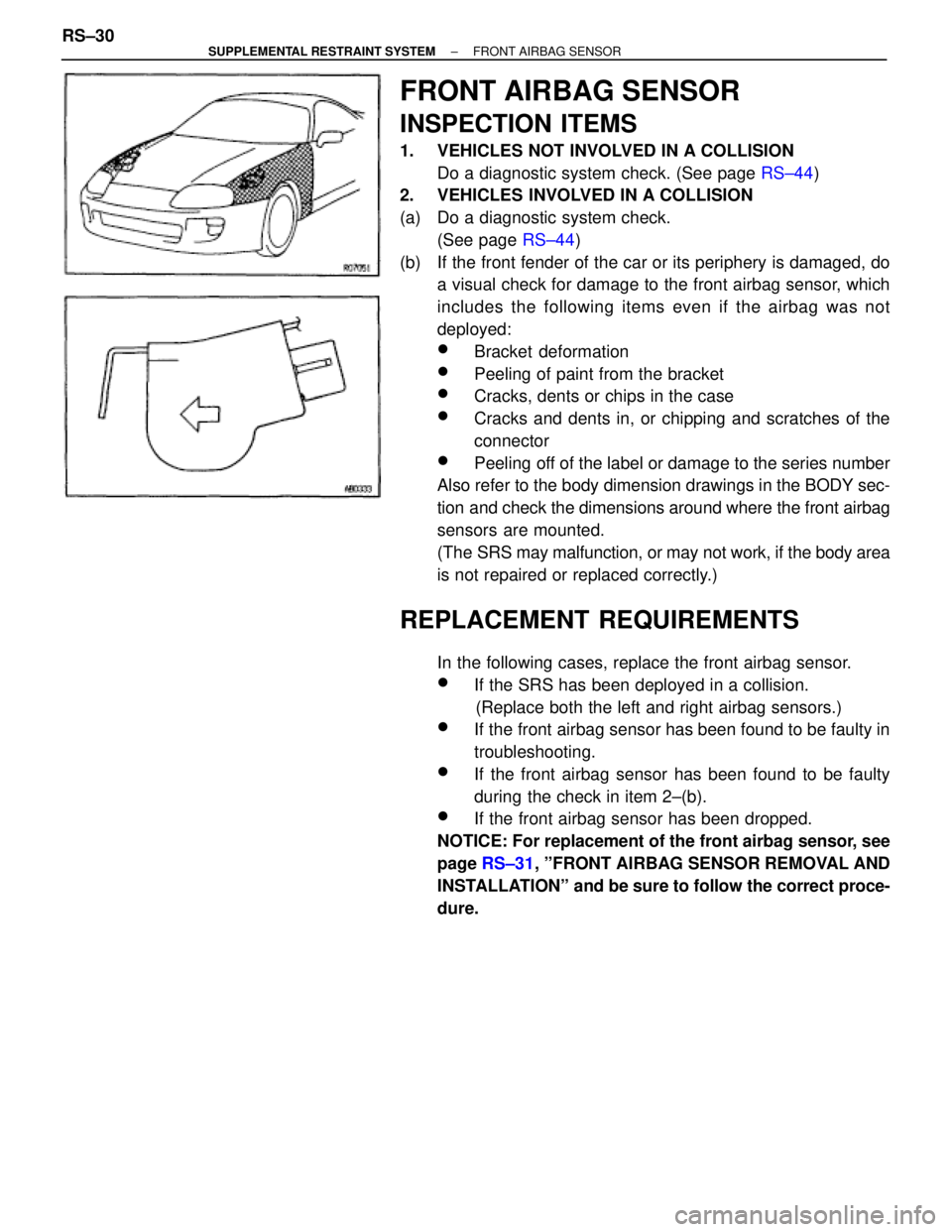
FRONT AIRBAG SENSOR
INSPECTION ITEMS
1. VEHICLES NOT INVOLVED IN A COLLISION
Do a diagnostic system check. (See page RS±44)
2. VEHICLES INVOLVED IN A COLLISION
(a) Do a diagnostic system check.
(See page RS±44)
(b) If the front fender of the car or its periphery is damaged, do
a visual check for damage to the front airbag sensor, which
includes the following items even if the airbag was not
deployed:
wBracket deformation
wPeeling of paint from the bracket
wCracks, dents or chips in the case
wCracks and dents in, or chipping and scratches of the
connector
wPeeling off of the label or damage to the series number
Also refer to the body dimension drawings in the BODY sec-
tion and check the dimensions around where the front airbag
sensors are mounted.
(The SRS may malfunction, or may not work, if the body area
is not repaired or replaced correctly.)
REPLACEMENT REQUIREMENTS
In the following cases, replace the front airbag sensor.
wIf the SRS has been deployed in a collision.
(Replace both the left and right airbag sensors.)
wIf the front airbag sensor has been found to be faulty in
troubleshooting.
wIf the front airbag sensor has been found to be faulty
during the check in item 2±(b).
wIf the front airbag sensor has been dropped.
NOTICE: For replacement of the front airbag sensor, see
page RS±31, ºFRONT AIRBAG SENSOR REMOVAL AND
INSTALLATIONº and be sure to follow the correct proce-
dure. RS±30
± SUPPLEMENTAL RESTRAINT SYSTEMFRONT AIRBAG SENSOR
Page 1715 of 2543

1. REMOVE FRONT FENDER LINER AND HEADLIGHT
2. REMOVE FRONT AIRBAG SENSOR
(a) Disconnect the connector.
(b) Remove the bolt, the nut and the sensor.
3. INSTALL FRONT AIRBAG SENSOR
Install the sensor with the arrow on the sensor facing toward
the front of the vehicle.
Torque: 29 NVm (300 kgfVcm, 22 ftVlbf)
NOTICE:
wMake sure the sensor is installed to the specified torque.
wIf the sensor has been dropped, or there are cracks, dents
or other defects in the case, brackets or connector,
replace the sensor is removed, always replace the set bolt
and the nut with new ones.
wThe sensor set bolt and the nut have been anti±rust
treated. When the sensor is removed, always replace the
set bolt and the nut with new ones.
wAfter installation, shake the sensor to check that there is
no looseness.
wThe front sensor is equipped with an electrical
connection check mechanism. Be sure to lock this
mechanism securely when connecting the connector. If
the connector is not securely locked, a malfunction code
will be detected by the diagnosis system.
wCheck that the dimensions of the body where the front
airbag sensor is installed match those in the body
dimension drawings in the BODY section. (The SRS may
malfunction, or may not work, if the dimensions of the
sensor mount is not correct.)
4. INSTALL HEADLIGHT AND FRONT FENDER LINER RS±32
± SUPPLEMENTAL RESTRAINT SYSTEMFRONT AIRBAG SENSOR