Page 1444 of 2543
5. INSTALL REAR CENTER FLOOR CROSSMEMBER
BRACE
Torque: 28 NVm (290 kgfVcm, 21 ftVlbf)
6. INSTALL EXHAUST PIPE HEAT INSULATOR
7. INSTALL NO.2 FRONT EXHAUST PIPE
Install a new gasket and the front exhaust pipe with 3 new
nuts.
Torque: 62 NVm (630 kgfVcm, 46 ftVlbf)
8. INSTALL EXHAUST PIPE ASSEMBLY
(a) Install the hook of the tailpipe to the 2 rings on the tailpipe
bracket.
(b) Install the hook of the exhaust pipe to the 2 rings on the
exhaust pipe brackets.
(c) Install the pipe support bracket with the 2 bolts.
Torque: 43 NVm (440 kgfVcm, 32 ftVlbf)
(d) Install a new gasket and the No.2 front exhaust pipe to the
front exhaust pipe with the 2 bolts and 2 new nuts.
Torque: 58 NVm (590 kgfVcm, 43 ftVlbf)
9. INSTALL SUB HEATED OXYGEN SENSOR
Install a new gasket, the oxygen sensor and sensor cover
with the 2 nuts.
Torque: 18 NVm (180 kgfVcm, 13 ftVlbf)
10. M/T:
INSTALL CLUTCH RELEASE CYLINDER AND GROUND
STRAP
(a) Install the clutch release cylinder with the 2 bolts.
Torque: 13 NVm (130 kgfVcm, 9 ftVlbf)
(b) Connect the clutch line tube with the bolt.
Torque: 37 NVm (380 kgfVcm, 27 ftVlbf)
(c) Install the ground strap with the bolt.
Torque: 37 NVm (380 kgfVcm, 27 ftVlbf)
11. CONNECT ENGINE WIRE TO CABIN
(a) Push in the engine wire through the cowl panel.
NOTICE: Be careful not to damage the engine wire.
(b) Connect the 2 connectors to the connector cassette.
(c) Connect the connector to the instrument panel wire
connector.
(d) Connect the 2 connectors to the ECM.
(e) Connect the connector to the TRAC ECU.
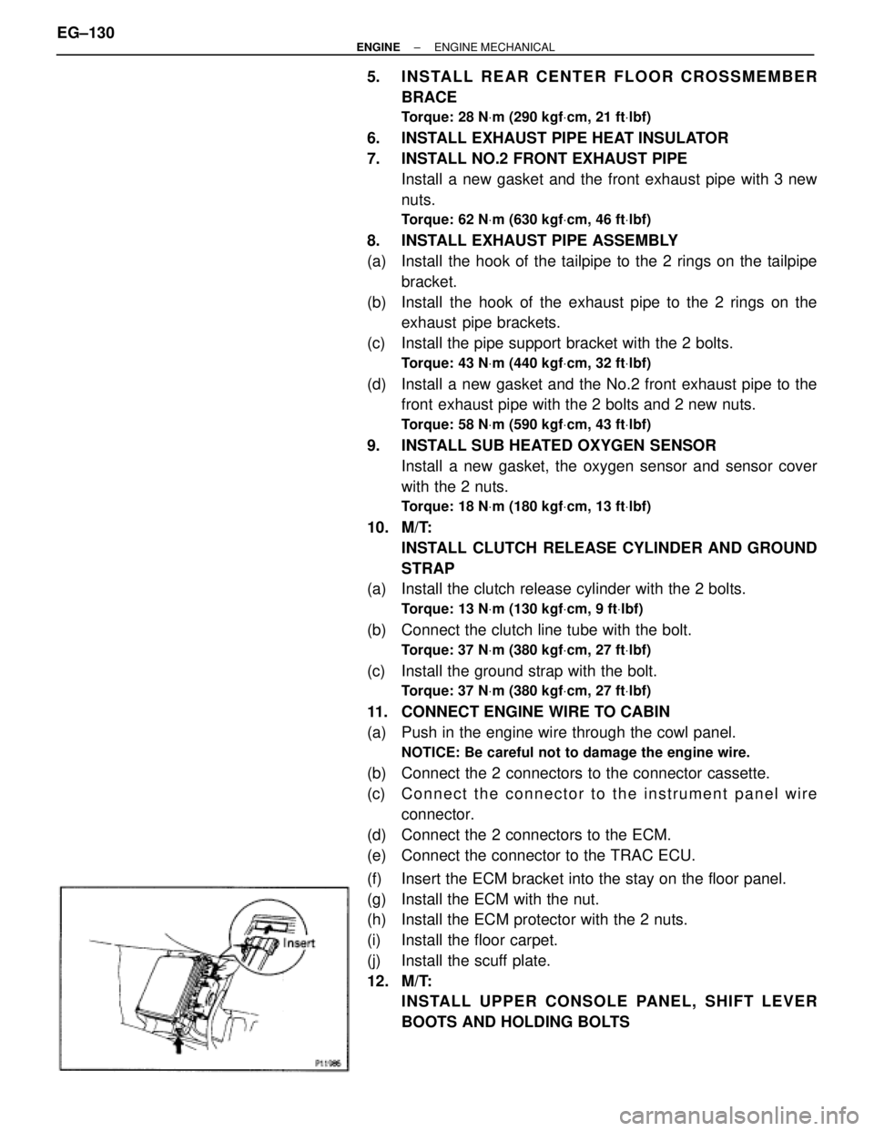
(f) Insert the ECM bracket into the stay on the floor panel.
(g) Install the ECM with the nut.
(h) Install the ECM protector with the 2 nuts.
(i) Install the floor carpet.
(j) Install the scuff plate.
12. M/T:
INSTALL UPPER CONSOLE PANEL, SHIFT LEVER
BOOTS AND HOLDING BOLTS EG±130
± ENGINEENGINE MECHANICAL
Page 1645 of 2543
STEERING COLUMN REMOVAL
1. REMOVE STEERING WHEEL PAD
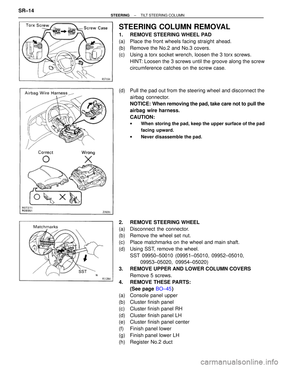
(a) Place the front wheels facing straight ahead.
(b) Remove the No.2 and No.3 covers.
(c) Using a torx socket wrench, loosen the 3 torx screws.
HINT: Loosen the 3 screws until the groove along the screw
circumference catches on the screw case.
(d) Pull the pad out from the steering wheel and disconnect the
airbag connector.
NOTICE: When removing the pad, take care not to pull the
airbag wire harness.
CAUTION:
wWhen storing the pad, keep the upper surface of the pad
facing upward.
wNever disassemble the pad.
2. REMOVE STEERING WHEEL
(a) Disconnect the connector.
(b) Remove the wheel set nut.
(c) Place matchmarks on the wheel and main shaft.
(d) Using SST, remove the wheel.
SST 09950±50010 (09951±05010, 09952±05010,
09953±05020, 09954±05020)
3. REMOVE UPPER AND LOWER COLUMN COVERS
Remove 5 screws.
4. REMOVE THESE PARTS:
(See page BO±45)
(a) Console panel upper
(b) Cluster finish panel
(c) Cluster finish panel RH
(d) Cluster finish panel LH
(e) Cluster finish panel center
(f) Finish panel lower
(g) Finish panel lower LH
(h) Register No.2 duct SR±14
± STEERINGTILT STEERING COLUMN
Page 1652 of 2543
STEERING COLUMN INSTALLATION
1. INSTALL STEERING COLUMN ASSEMBLY
(a) Torque the 4 column assembly set nuts.
Torque: 25 NVm (260 kgfVcm, 19 ftVlbf)
(b) Install the brake pedal return spring.
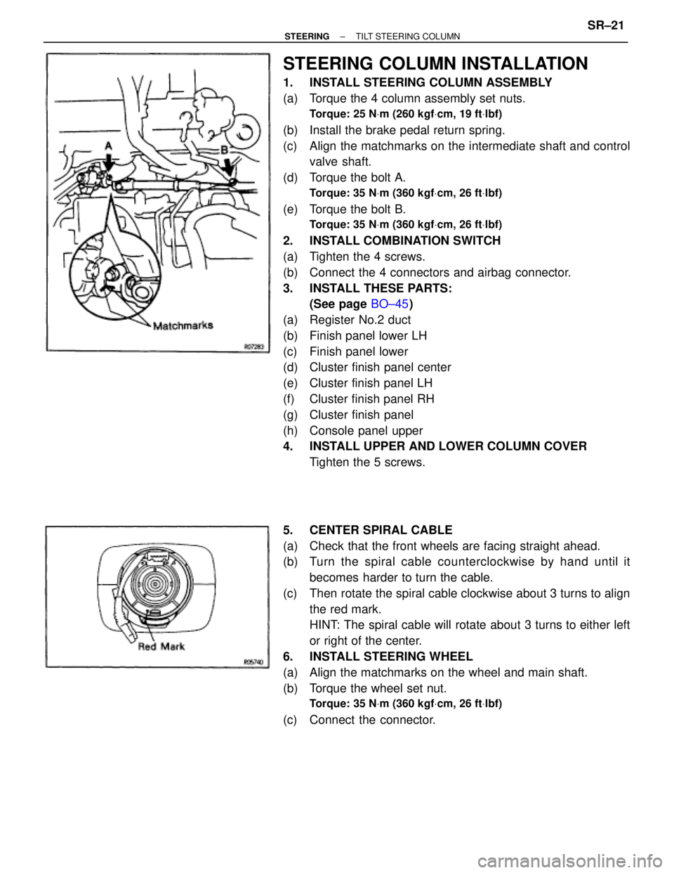
(c) Align the matchmarks on the intermediate shaft and control
valve shaft.
(d) Torque the bolt A.
Torque: 35 NVm (360 kgfVcm, 26 ftVlbf)
(e) Torque the bolt B.
Torque: 35 NVm (360 kgfVcm, 26 ftVlbf)
2. INSTALL COMBINATION SWITCH
(a) Tighten the 4 screws.
(b) Connect the 4 connectors and airbag connector.
3. INSTALL THESE PARTS:
(See page BO±45)
(a) Register No.2 duct
(b) Finish panel lower LH
(c) Finish panel lower
(d) Cluster finish panel center
(e) Cluster finish panel LH
(f) Cluster finish panel RH
(g) Cluster finish panel
(h) Console panel upper
4. INSTALL UPPER AND LOWER COLUMN COVER
Tighten the 5 screws.
5. CENTER SPIRAL CABLE
(a) Check that the front wheels are facing straight ahead.
(b) Turn the spiral cable counterclockwise by hand until it
becomes harder to turn the cable.
(c) Then rotate the spiral cable clockwise about 3 turns to align
the red mark.
HINT: The spiral cable will rotate about 3 turns to either left
or right of the center.
6. INSTALL STEERING WHEEL
(a) Align the matchmarks on the wheel and main shaft.
(b) Torque the wheel set nut.
Torque: 35 NVm (360 kgfVcm, 26 ftVlbf)
(c) Connect the connector.
± STEERINGTILT STEERING COLUMNSR±21
Page 1688 of 2543
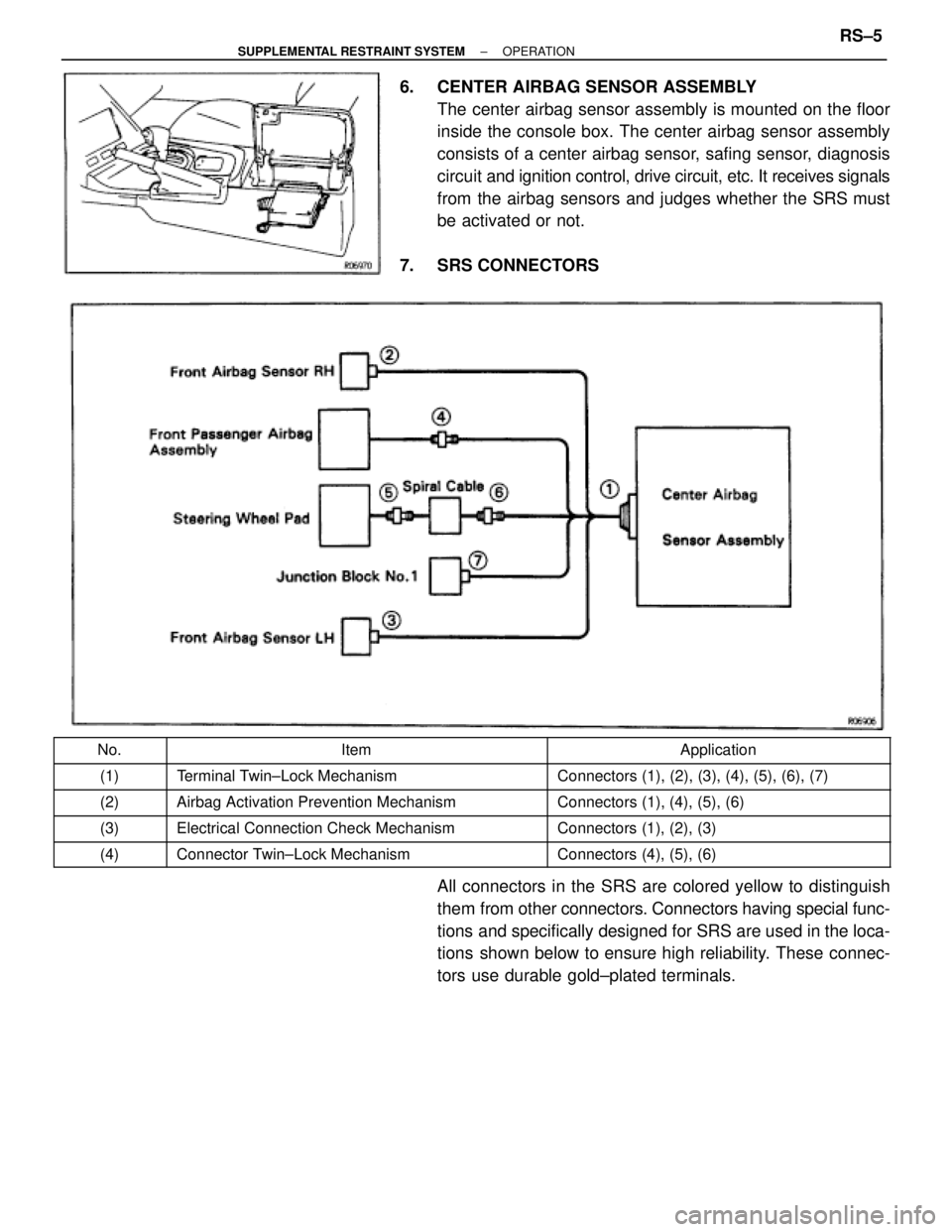
6. CENTER AIRBAG SENSOR ASSEMBLY
The center airbag sensor assembly is mounted on the floor
inside the console box. The center airbag sensor assembly
consists of a center airbag sensor, safing sensor, diagnosis
circuit and ignition control, drive circuit, etc. It receives signals
from the airbag sensors and judges whether the SRS must
be activated or not.
7. SRS CONNECTORS
����� �����No.����������������� �����������������Item���������������� ����������������Application����� �
���� �����(1)
����������������� �
���������������� ����������������� Terminal Twin±Lock Mechanism
���������������� �
��������������� ���������������� Connectors (1), (2), (3), (4), (5), (6), (7)
����� �����(2)����������������� ����������������� Airbag Activation Prevention Mechanism���������������� ���������������� Connectors (1), (4), (5), (6)
����� �����(3)����������������� ����������������� Electrical Connection Check Mechanism���������������� ���������������� Connectors (1), (2), (3)
����� �����(4)����������������� ����������������� Connector Twin±Lock Mechanism���������������� ���������������� Connectors (4), (5), (6)
All connectors in the SRS are colored yellow to distinguish
them from other connectors. Connectors having special func-
tions and specifically designed for SRS are used in the loca-
tions shown below to ensure high reliability. These connec-
tors use durable gold±plated terminals.
± SUPPLEMENTAL RESTRAINT SYSTEMOPERATIONRS±5
Page 1718 of 2543
wNever use SRS parts from another vehicle. When
replacing parts, replace with new parts.
wNever reuse the center airbag sensor assembly involved
in a collision when the airbag has deployed.
wNever repair a sensor in order to reuse it.
1. REMOVE CONSOLE PANEL UPPER AND CONSOLE BOX
(See page BO±44)
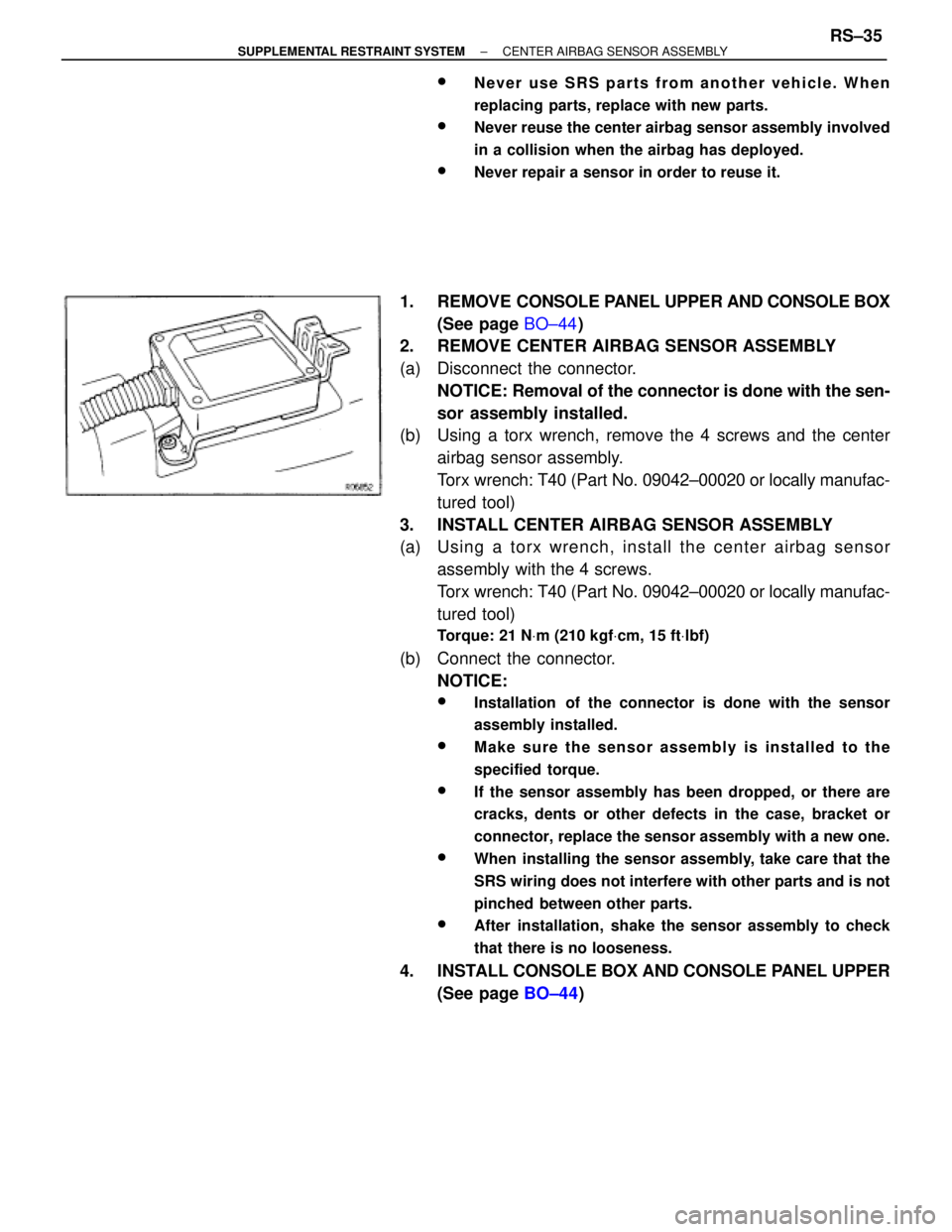
2. REMOVE CENTER AIRBAG SENSOR ASSEMBLY
(a) Disconnect the connector.
NOTICE: Removal of the connector is done with the sen-
sor assembly installed.
(b) Using a torx wrench, remove the 4 screws and the center
airbag sensor assembly.
Torx wrench: T40 (Part No. 09042±00020 or locally manufac-
tured tool)
3. INSTALL CENTER AIRBAG SENSOR ASSEMBLY
(a) Usin g a to rx wre n ch , in sta ll th e ce n te r airb a g se n so r
assembly with the 4 screws.
Torx wrench: T40 (Part No. 09042±00020 or locally manufac-
tured tool)
Torque: 21 NVm (210 kgfVcm, 15 ftVlbf)
(b) Connect the connector.
NOTICE:
wInstallation of the connector is done with the sensor
assembly installed.
wMake sure the sensor assembly is installed to the
specified torque.
wIf the sensor assembly has been dropped, or there are
cracks, dents or other defects in the case, bracket or
connector, replace the sensor assembly with a new one.
wWhen installing the sensor assembly, take care that the
SRS wiring does not interfere with other parts and is not
pinched between other parts.
wAfter installation, shake the sensor assembly to check
that there is no looseness.
4. INSTALL CONSOLE BOX AND CONSOLE PANEL UPPER
(See page BO±44)
± SUPPLEMENTAL RESTRAINT SYSTEMCENTER AIRBAG SENSOR ASSEMBLYRS±35