Page 31 of 2543

(See page AC±26)
(See page IN±30).
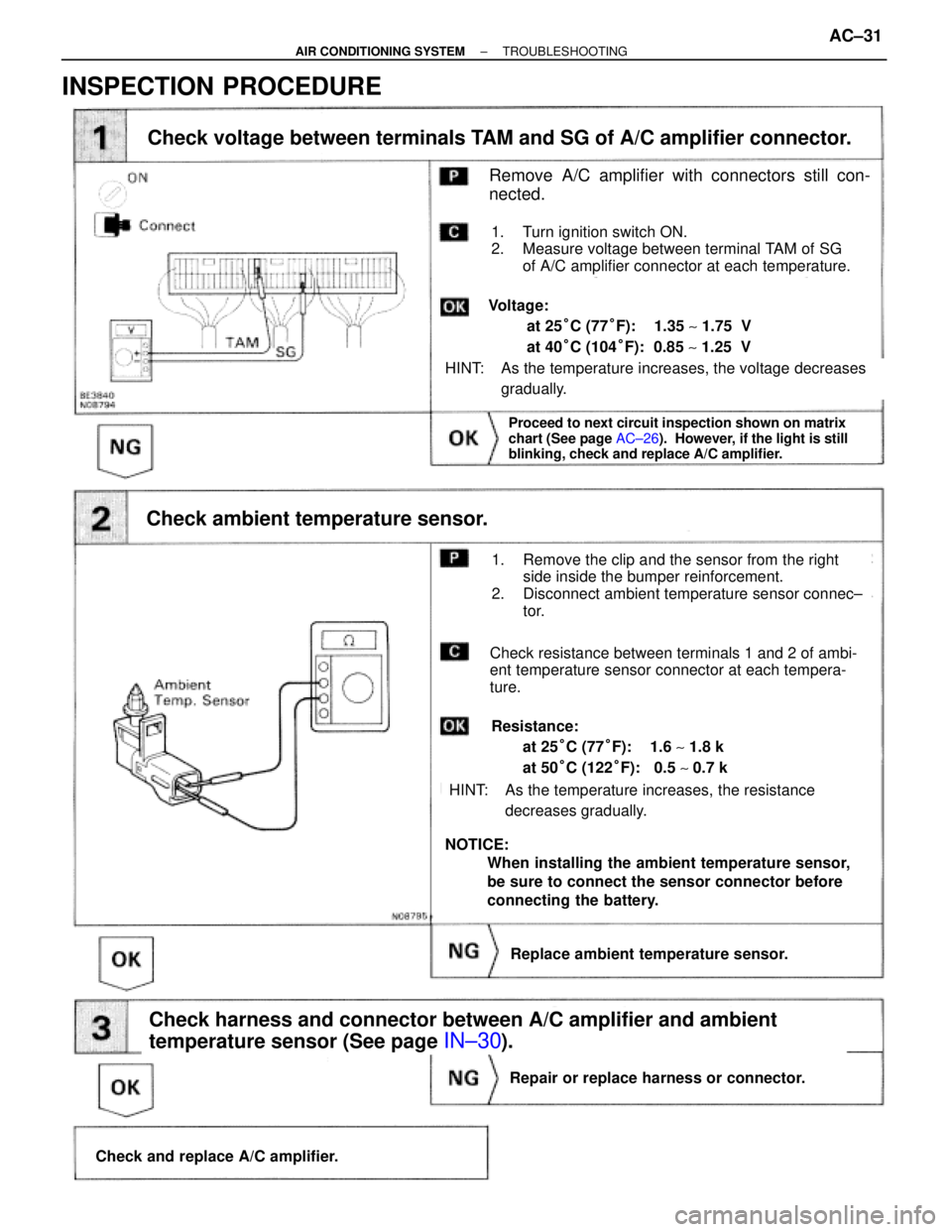
Check voltage between terminals TAM and SG of A/C amplifier connector.
Check ambient temperature sensor.
Check harness and connector between A/C amplifier and ambient
temperature sensor (See page
IN±30).
Proceed to next circuit inspection shown on matrix
chart (See page AC±26). However, if the light is still
blinking, check and replace A/C amplifier.
Check and replace A/C amplifier.
Repair or replace harness or connector.
Replace ambient temperature sensor.
Remove A/C amplifier with connectors still con-
nected.
1. Turn ignition switch ON.
2. Measure voltage between terminal TAM of SG
of A/C amplifier connector at each temperature.
HINT: As the temperature increases, the voltage decreases
gradually.
Voltage:
at 25°C (77°F): 1.35 ~ 1.75 V
at 40°C (104°F): 0.85 ~ 1.25 V
1. Remove the clip and the sensor from the right
side inside the bumper reinforcement.
2. Disconnect ambient temperature sensor connec±
tor.
Check resistance between terminals 1 and 2 of ambi-
ent temperature sensor connector at each tempera-
ture.
Resistance:
at 25°C (77°F): 1.6 ~ 1.8 k�
at 50°C (122°F): 0.5 ~ 0.7 k�
HINT: As the temperature increases, the resistance
decreases gradually.
NOTICE:
When installing the ambient temperature sensor,
be sure to connect the sensor connector before
connecting the battery.
INSPECTION PROCEDURE
± AIR CONDITIONING SYSTEMTROUBLESHOOTINGAC±31
Page 51 of 2543

INSPECTION PROCEDURE
AC±22).
Check and replace A/C amplifier.
Repair or replace harness or connector.
Check for open and short in harness and connector between A/C amplifier and air outlet damper control
servo motor, air outlet damper control servo motor and battery, air outlet damper control servo motor
and body ground (See page IN±26).
Replace air outlet servo motor.
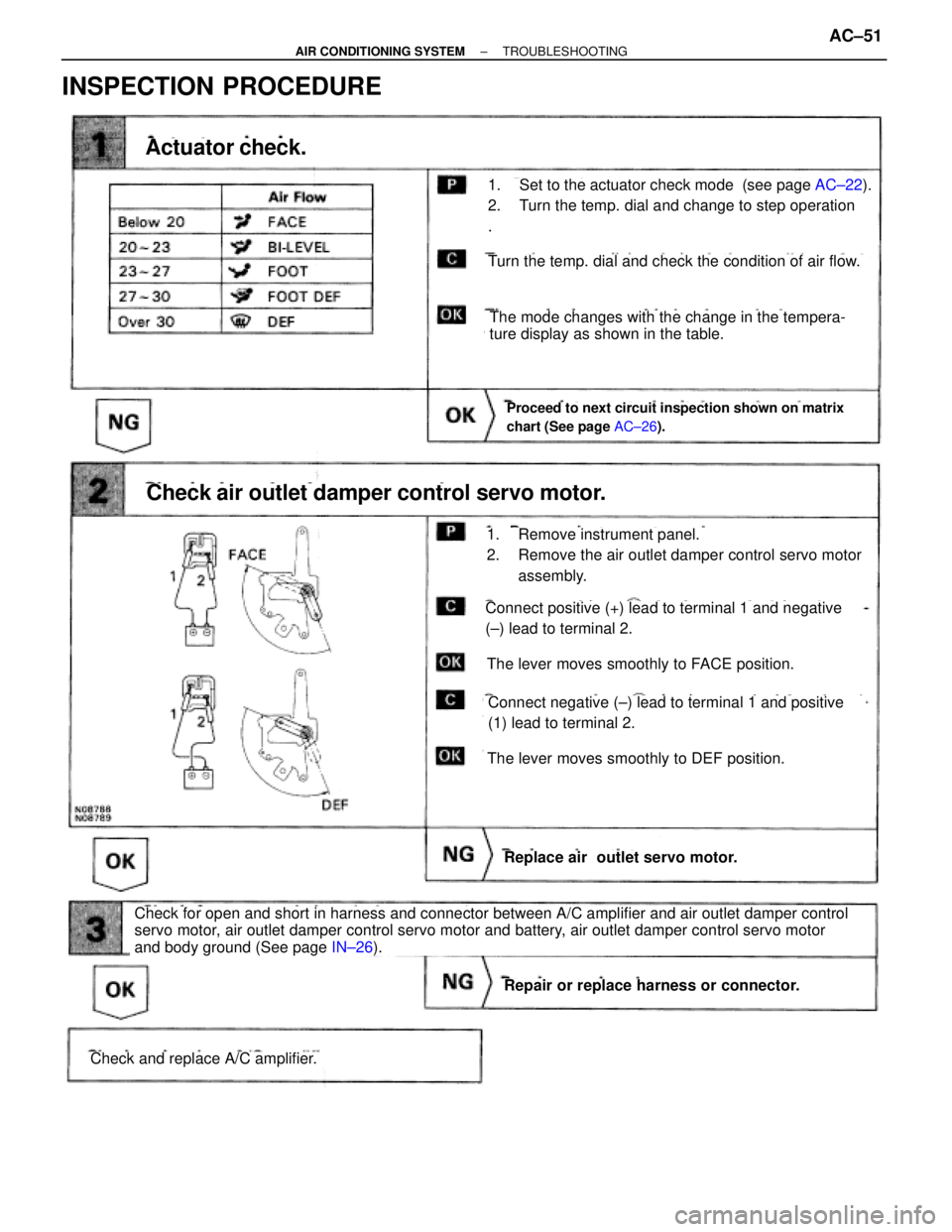
Check air outlet damper control servo motor.
Proceed to next circuit inspection shown on matrix
chart (See page AC±26).
Actuator check.
Turn the temp. dial and check the condition of air flow.
The mode changes with the change in the tempera-
ture display as shown in the table.
The lever moves smoothly to DEF position.
The lever moves smoothly to FACE position.
Connect positive (+) lead to terminal 1 and negative
(±) lead to terminal 2.
Connect negative (±) lead to terminal 1 and positive
(1) lead to terminal 2.
1. Remove instrument panel.
2. Remove the air outlet damper control servo motor
assembly.
1. Set to the actuator check mode (see page AC±22).
2. Turn the temp. dial and change to step operation
.
± AIR CONDITIONING SYSTEMTROUBLESHOOTINGAC±51
Page 53 of 2543
INSPECTION PROCEDURE
Remove the A/C amplifier with connector still con-
ected.
Measure voltage between terminal + B of air condi-
tioner control assembly connector and body ground.
Voltage: Battery positive voltage
Proceed to next circuit inspection shown on matrix
chart (See page AC±26).
Remove ECU±B fuse from J/B No. 1.
Check continuity of ECU±B fuse.
Continuity
Check ECU±B fuse.
Check for short in all the harness and compo-
nents to the ECU±B fuse (See attached wiring
diagram).
Check voltage between terminal +B of A/C amplifier connector and
body ground.
Check and repair harness and connector between
A/C amplifier and battery.
± AIR CONDITIONING SYSTEMTROUBLESHOOTINGAC±53
Page 54 of 2543
IG Power Source Circuit
CIRCUIT DESCRIPTION
This is the power source for the A/C amplifier and servo motors, etc.
INSPECTION PROCEDURE
Remove the A/C amplifier with connector still con-
nected
Voltage: Battery positive voltage
1. Turn ignition switch ON.
2. Measure voltage between terminals IG and GND
of A/C amplifier.
Proceed to next circuit inspection shown on matrix
chart (See page AC±26).
Go to step
Check voltage between terminals IG and GND of A/C amplifier connector.
AC±54± AIR CONDITIONING SYSTEMTROUBLESHOOTING
Page 55 of 2543
Check continuity between terminal GND of A/C amplifier and body
ground.
Measure resistance between terminal GND of A/C
amplifier and body ground.
Remove HTR fuse from J/B No. 1.
Check continuity of HTR fuse.
Continuity
Check for short in all the harness and compo-
nents to the HTR fuse (See attached wiring
diagram).
Check and repair harness and connector between
A/C amplifier and battery.
Check HTR fuse.
Repair or replace harness or connector.
Resistance: O �� �continuity)
± AIR CONDITIONING SYSTEMTROUBLESHOOTINGAC±55
Page 57 of 2543
INSPECTION PROCEDURE
Check voltage between terminal ACC of A/C amplifier connector and
body ground.
Remove the A/C amplifier with connector still connected
Voltage: Battery positive voltage
1. Turn ignition switch To ACC.
2. Measure voltage between terminals ACC of A/C
amplifier connector and body ground.
Remove CIG fuse from J/B No. 1.
Check continuity of CIG fuse.
Continuity
Proceed to next circuit inspection shown on matrix
chart (See page AC±26).
Check CIG fuse.
Check for short in all the harness and compo-
nents to the CIG fuse (See attached wiring
diagram).
Check and repair harness and connector between
A/C amplifier and battery.
± AIR CONDITIONING SYSTEMTROUBLESHOOTINGAC±57
Page 59 of 2543

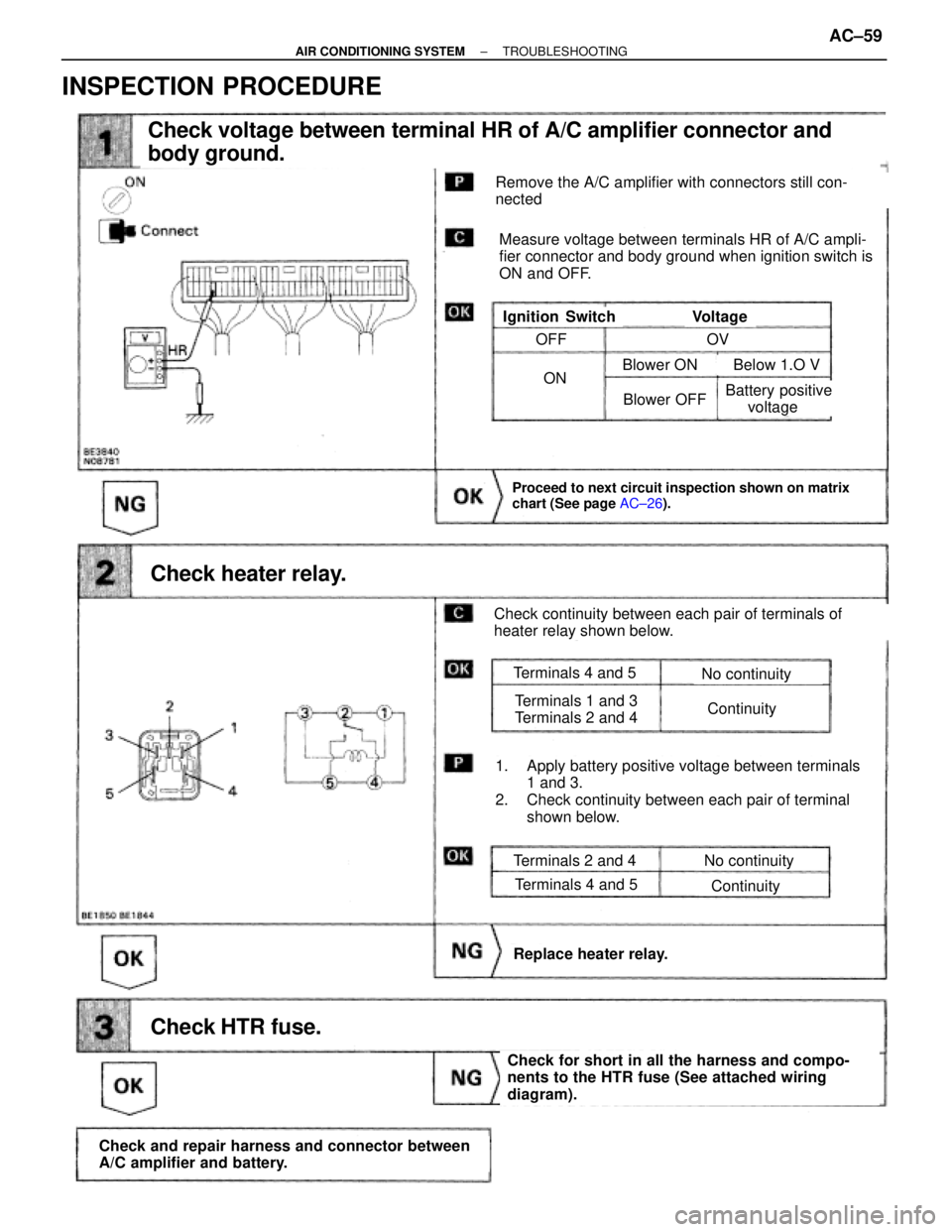
Check voltage between terminal HR of A/C amplifier connector and
body ground.
Check heater relay.
Proceed to next circuit inspection shown on matrix
chart (See page AC±26).
Check HTR fuse.
Check and repair harness and connector between
A/C amplifier and battery.
Check for short in all the harness and compo-
nents to the HTR fuse (See attached wiring
diagram).
Replace heater relay.
Remove the A/C amplifier with connectors still con-
nected
Measure voltage between terminals HR of A/C ampli-
fier connector and body ground when ignition switch is
ON and OFF.
VoltageIgnition Switch
Check continuity between each pair of terminals of
heater relay shown below.
1. Apply battery positive voltage between terminals
1 and 3.
2. Check continuity between each pair of terminal
shown below.
Terminals 2 and 4
Terminals 4 and 5
No continuity
Continuity
Terminals 4 and 5
Terminals 1 and 3
Terminals 2 and 4
No continuity
Continuity
OFF
ON
OV
Blower OFF
Blower ON Below 1.O V
Battery positive
voltage
INSPECTION PROCEDURE
± AIR CONDITIONING SYSTEMTROUBLESHOOTINGAC±59
Page 61 of 2543
(See page AC±99).
Check blower motor.
Go to step
Replace blower motor.
Check blower motor control relay.
Replace blower motor control relay.
Repair or replace harness or connector
Remove blower motor control relay with connectors
still connected
1. Turn ignition switch To ON.
2. Operate blower motor.
TerminalsStandard Value
Continuity
Battery Positive
Voltage
Battery Positive
Voltage
Battery Positive
Voltage
Connect positive (+) lead to terminal 2
of blower motor connector, negative (±) lead to
terminal 1.
Remove blower motor control (see page AC±99).
Blower motor operates smoothly.
± AIR CONDITIONING SYSTEMTROUBLESHOOTINGAC±61