Page 63 of 2543
Check voltage between terminal A/C IN of A/C amplifier connector and
body ground.
Check air conditioning compressor magnetic clutch.
Go to step
Check for open and short in harness and connector between air
conditioner compressor and magnetic clutch relay (See page IN±30).
Repair or replace harness or connector.
Go to step
1. Remove A/C amplifier with connectors still con
nected.
2. Start the engine.
Check voltage between terminal A/C IN of A/C amplifi-
er connector and body ground when magnetic clutch is
on and off by A/C switch.
Magnetic ClutchVoltage
ON
OFF Below 1 V
Connect positive (+) lead connected to battery to
magnetic clutch connector terminal 4.
Disconnect magnetic clutch connector.
Magnetic clutch is energized.
Repair air conditioning compressor magnetic
clutch.
10 ± 14 V
INSPECTION PROCEDURE
± AIR CONDITIONING SYSTEMTROUBLESHOOTINGAC±63
Page 65 of 2543

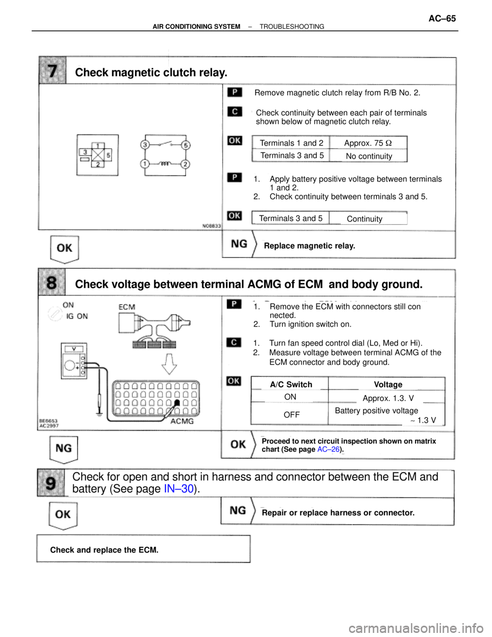
Remove magnetic clutch relay from R/B No. 2.
Check continuity between each pair of terminals
shown below of magnetic clutch relay.
Terminals 1 and 2
Terminals 3 and 5
Terminals 3 and 5
No continuity
Continuity
Replace magnetic relay.
Check and replace the ECM.
Repair or replace harness or connector.
A/C SwitchVoltage
ON
OFF
Check for open and short in harness and connector between the ECM and
battery (See page IN±30).
Approx. 1.3. V
Approx. 75 �
Battery positive voltage
Check magnetic clutch relay.
Check voltage between terminal ACMG of ECM and body ground.
1. Apply battery positive voltage between terminals
1 and 2.
2. Check continuity between terminals 3 and 5.
1. Remove the ECM with connectors still con
nected.
2. Turn ignition switch on.
1. Turn fan speed control dial (Lo, Med or Hi).
2. Measure voltage between terminal ACMG of the
ECM connector and body ground.
Proceed to next circuit inspection shown on matrix
chart (See page AC±26).
~ 1.3 V
± AIR CONDITIONING SYSTEMTROUBLESHOOTINGAC±65
Page 86 of 2543
COMPRESSOR REMOVAL
1. RUN ENGINE AT IDLE SPEED WITH A/C ON FOR
APPROX. 10 MINUTES
2. STOP ENGINE
3. REMOVE BATTERY
4. DISCHARGE REFRIGERANT IN REFRIGERATION
SYSTEM
5. REMOVE DRIVE BELT
Loosen the drive belt tension by turning the drive belt tension-
er clockwise, and remove the drive belt.
6. REMOVE POWER STEERING PUMP
7. DISCONNECT DISCHARGE HOSE AND SUCTION HOSE
FROM COMPRESSOR
NOTICE: Cap the open fittings immediately to keep mois-
ture out of the system.
8. REMOVE COMPRESSOR
(a) Disconnect connector from compressor.
(b) Remove engine under cover.
(d) Remove the 4 bolts, nut and stud bolt.
(d) Remove the compressor. AC±86
± AIR CONDITIONING SYSTEMCOMPRESSOR
Page 89 of 2543
3. REMOVE STATOR
(a) Disconnect the stator lead wire from the compressor
housing.
(b) Using SST, remove the snap ring.
SST 07114±84020
ASSEMBLY NOTICE: The snap ring should be installed
so that its beveled side faces up.
(c) Remove the stator.
MAGNETIC CLUTCH ASSEMBLY
Assembly is in the reverse order of disassembly.
CHECK CLEARANCE OF MAGNETIC CLUTCH
(a) Set the dial±gauge to the pressure plate of the magnetic
clutch.
(b) Connect the magnetic clutch lead wire to the positive (+)
terminal of the battery.
± AIR CONDITIONING SYSTEMCOMPRESSORAC±89
Page 90 of 2543

(c) Check the clearance between the pressure plate and rotor,
then connect the negative (±) terminal of the battery.
Standard clearance:
0.5 + 0.15 mm (0.020 + 0.0059 in.)
If the clearance is not within specification, adjust the clear-
ance using shims to obtain the standard clearance.
Shim Thickness:
0.1 mm (0.004 in.)
0.3 mm (0.012 in.)
0.5 mm (0.020 in.)
COMPRESSOR INSTALLATION
1. INSTALL COMPRESSOR
(a) Install the stud bolt.
Torque: 26 NVm (265 kgfVcm, 19 ftVlbf)
(b) Install the compressor with 4 bolts and nut.
Torque: 52 NVm (530 kgfVcm, 38 ftVlbf)
(c) Connect the magnetic clutch connector.
(d) Install the engine under cover.
2. CONNECT DISCHARGE HOSE AND SUCTION HOSE TO
COMPRESSOR
NOTICE: Hoses should be connected immediately after
the caps have been removed.
Torque: 10 NVm (100 kgfVcm, 7 ftVlbf)
3. INSTALL POWER STEERING PUMP
Install the power steering pump with 2 bolts.
Torque: 58 NVm (590 kgfVcm, 43 ftVlbf)
4. INSTALL DRIVE BELT
5. INSTALL BATTERY
6. EVACUATE AIR IN REFRIGERATION SYSTEM AND
CHARGE WITREFRIGERANT
Specified amount:
700 + 50 g (24.96 + 1.76 oz.)
7. INSPECT FOR LEAKAGE OF REFRIGERANT
Using a gas leak tester, check for leakage of refrigerant.
If there is leakage, check the tightening torque at the joints.
8. INSPECT A/C OPERATION AC±90
± AIR CONDITIONING SYSTEMCOMPRESSOR
Page 92 of 2543

CONDENSER
ON±VEHICLE INSPECTION
1. INSPECT CONDENSER FINS FOR BLOCKAGE OR
DAMAGE
If fins are clogged, wash them with water and dry with com-
pressed air.
NOTICE: Be careful not to damage the fins.
If fins are bent, straighten them with a screwdriver or pliers.
2. INSPECT CONDENSER AND FITTING FOR LEAKAGE
Using a gas leak tester, check for leakage.
If there is leakage, check the tightening torque at the joints.
CONDENSER REMOVAL
1. DISCHARGE REFRIGERANT IN REFRIGERATION
SYSTEM
INSTALLATION HINT: Evacuate air from refrigeration sys-
tem.
Charge system with refrigerant and inspect for leakage of re-
frigerant.
Specified amount:
700 +50g (24.96 +1.76 oz.)
2. REMOVE BATTERY
3. REMOVE AIR CLEANER DUCT
Remove the bolt and the air cleaner duct.
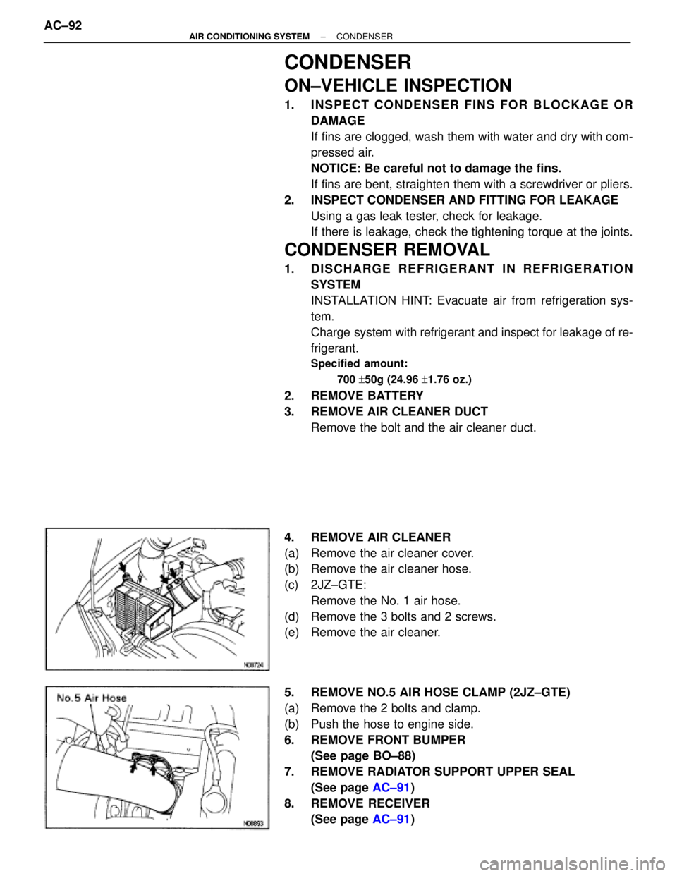
4. REMOVE AIR CLEANER
(a) Remove the air cleaner cover.
(b) Remove the air cleaner hose.
(c) 2JZ±GTE:
Remove the No. 1 air hose.
(d) Remove the 3 bolts and 2 screws.
(e) Remove the air cleaner.
5. REMOVE NO.5 AIR HOSE CLAMP (2JZ±GTE)
(a) Remove the 2 bolts and clamp.
(b) Push the hose to engine side.
6. REMOVE FRONT BUMPER
(See page BO±88)
7. REMOVE RADIATOR SUPPORT UPPER SEAL
(See page AC±91)
8. REMOVE RECEIVER
(See page AC±91) AC±92
± AIR CONDITIONING SYSTEMCONDENSER
Page 107 of 2543
ELECTRIC COOLING FAN
ON±VEHICLE INSPECTION
Condenser Fan:
1. INSPECT CONDENCER
(a) Disconnect the fan connector.
(b) Connect battery and ammeter to the cooling fan connector.
(c) Check that the condenser fan rotates smoothly, and check
the reading on the ammeter.
Standard amperage:
6.0±7.4 A
(d) Reconect the fan connector.
2. CONNECT NEGATIVE (±) TERMINAL CABLE TO
BATTERY
Radiator Fan:
(See page EG±353)
COOLING FAN RELAYS INSPECTION
(See page EG±356)
ECT SWITCH
(in ENGINE RADIATOR)
(See page EG±356)
± AIR CONDITIONING SYSTEMELECTRIC COOLING FANAC±107
Page 115 of 2543

INTRODUCTIONGENERAL REPAIR INSTRUCTIONS -
IN-4
GENERAL REPAIR INSTRUCTIONS
1. Use fender, seat and floor covers to keep the vehicle
clean and prevent damage.
2. During disassembly, keep parts in the appropriate order
to facilitate reassembly.
3. Observe the following:
(a) Before performing electrical work, disconnect the
negative cable from the battery terminal.
(b) If it is necessary to disconnect the battery for inspec-
tion or repair, always disconnect the cable from the
negative (-) terminal which is grounded to the ve-
hicle body.
(c) To prevent damage to the battery terminal post, loos-
en the terminal nut and raise the cable straight up
without twisting or prying it.
(d) Clean the battery terminal posts and cable terminals
with a clean shop rag. Do not scrape them with a file
or other abrasive objects.
(e) Install the cable terminal to the battery post with the
nut loose, and tighten the nut after installation. Do
not use a hammer to tap the terminal onto the post.
(f) Be sure the cover for the positive (+) terminal is prop-
erly in place.
4. Check hose and wiring connectors to make sure that they
are secure and correct.
5. Non-reusable parts
(a) Always replace cotter pins, gaskets, O-rings and oil
seals etc. with new ones.
(b) Non-reusable parts are indicated in the component
illustrations by the º�º symbol.
6. Precoated parts
Precoated parts are bolts and nuts, etc. that are coated
with a seal lock adhesive at the factory.
(a) If a precoated part is retightened, loosened or
caused to move in any way, it must be recoated with
the specified adhesive.
(b) When reusing precoated parts, clean off the old
adhesive and dry with compressed air. Then applyIN022-02