Page 407 of 2543

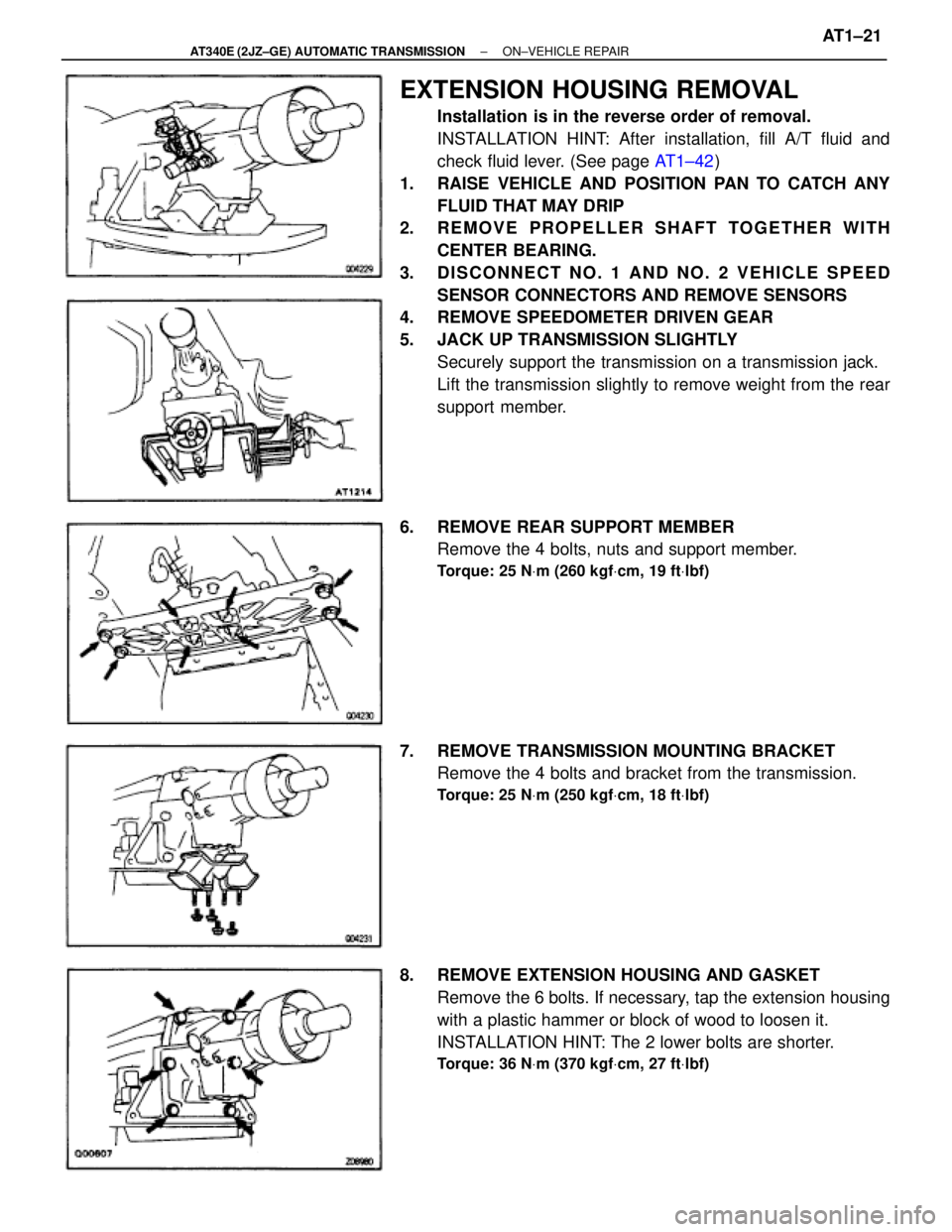
EXTENSION HOUSING REMOVAL
Installation is in the reverse order of removal.
INSTALLATION HINT: After installation, fill A/T fluid and
check fluid lever. (See page AT1±42)
1. RAISE VEHICLE AND POSITION PAN TO CATCH ANY
FLUID THAT MAY DRIP
2. REMOVE PROPELLER SHAFT TOGETHER WITH
CENTER BEARING.
3. DISCONNECT NO. 1 AND NO. 2 VEHICLE SPEED
SENSOR CONNECTORS AND REMOVE SENSORS
4. REMOVE SPEEDOMETER DRIVEN GEAR
5. JACK UP TRANSMISSION SLIGHTLY
Securely support the transmission on a transmission jack.
Lift the transmission slightly to remove weight from the rear
support member.
6. REMOVE REAR SUPPORT MEMBER
Remove the 4 bolts, nuts and support member.
Torque: 25 NVm (260 kgfVcm, 19 ftVlbf)
7. REMOVE TRANSMISSION MOUNTING BRACKET
Remove the 4 bolts and bracket from the transmission.
Torque: 25 NVm (250 kgfVcm, 18 ftVlbf)
8. REMOVE EXTENSION HOUSING AND GASKET
Remove the 6 bolts. If necessary, tap the extension housing
with a plastic hammer or block of wood to loosen it.
INSTALLATION HINT: The 2 lower bolts are shorter.
Torque: 36 NVm (370 kgfVcm, 27 ftVlbf)
± AT340E (2JZ±GE) AUTOMATIC TRANSMISSIONON±VEHICLE REPAIRAT1±21
Page 1223 of 2543
INSTALLATION HINT:
Use a new gasket (2JZ±GE) or O±ring (2JZ±GTE).
Torque:
2JZ±GE
49 NVm (500 kgfVcm, 36 ftVlbf)
2JZ±GTE
29 NVm (300 kgfVcm, 22 ftVlbf)
2. REMOVE DRIVE AND DRIVEN ROTORS
Remove the 10 screws, pump body cover, the drive and driv-
en rotors.
Torque: 10 NVm (105 kgfVcm, 8.0 ftVlbf)
ASSEMBLY HINT: Place the drive and driven rotors into the
oil pump body with the mark facing upward.
OIL PUMP INSPECTION
1. INSPECT RELIEF VALVE
Coat the valve with engine oil and check that it falls smoothly
into the valve hole under its own weight.
If it doesn't, replace the relief valve. If necessary, replace the
oil pump assembly.
2. INSPECT DRIVE AND DRIVEN ROTORS
A. Place drive and driven rotors into oil pump body
ASSEMBLY HINT: Place the drive and driven rotors into the
oil pump body with the mark facing upward.
± ENGINELUBRICATION SYSTEMEG±371
Page 1659 of 2543

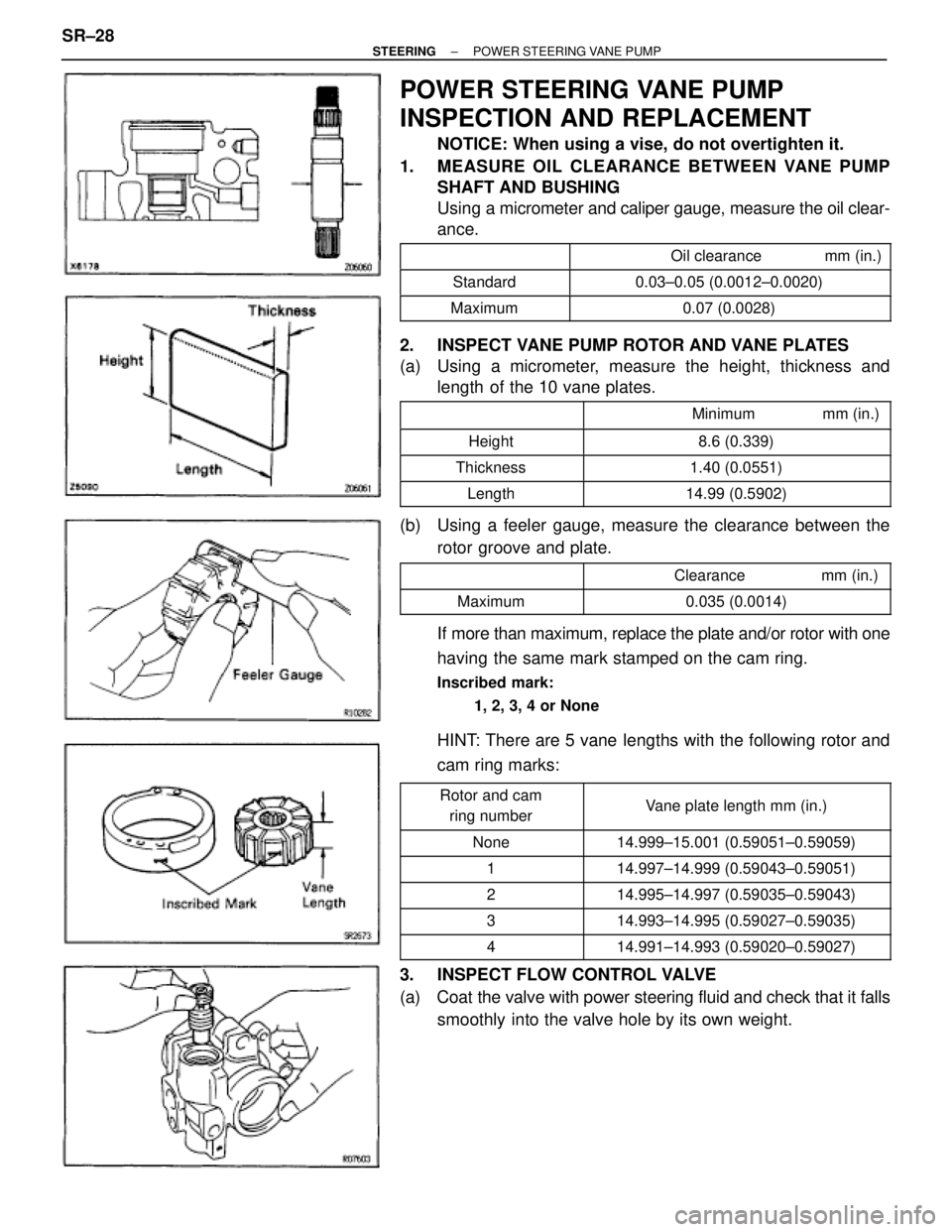
POWER STEERING VANE PUMP
INSPECTION AND REPLACEMENT
NOTICE: When using a vise, do not overtighten it.
1. MEASURE OIL CLEARANCE BETWEEN VANE PUMP
SHAFT AND BUSHING
Using a micrometer and caliper gauge, measure the oil clear-
ance.
�������� ����������������������� ��������������� Oil clearance mm (in.)
�������� ��������Standard��������������� ���������������0.03±0.05 (0.0012±0.0020)
�������� ��������Maximum��������������� ���������������0.07 (0.0028)
2. INSPECT VANE PUMP ROTOR AND VANE PLATES
(a) Using a micrometer, measure the height, thickness and
length of the 10 vane plates.
��������� ����������������������� �������������� Minimum mm (in.)��������� �
�������� ���������Height
�������������� �
������������� ��������������8.6 (0.339)
��������� ���������Thickness�������������� ��������������1.40 (0.0551)
��������� ���������Length�������������� ��������������14.99 (0.5902)
(b) Using a feeler gauge, measure the clearance between the
rotor groove and plate.
��������� ����������������������� �������������� Clearance mm (in.)
��������� ���������Maximum�������������� ��������������0.035 (0.0014)
If more than maximum, replace the plate and/or rotor with one
having the same mark stamped on the cam ring.
Inscribed mark:
1, 2, 3, 4 or None
HINT: There are 5 vane lengths with the following rotor and
cam ring marks:
��������� �
�������� ���������Rotor and cam
ring number�������������� �
������������� ��������������Vane plate length mm (in.)
��������� ���������None�������������� ��������������14.999±15.001 (0.59051±0.59059)��������� ���������1�������������� ��������������14.997±14.999 (0.59043±0.59051)��������� �
��������2
�������������� �
�������������14.995±14.997 (0.59035±0.59043)��������� �
�������� ���������3
�������������� �
������������� ��������������14.993±14.995 (0.59027±0.59035)
��������� ���������4�������������� ��������������14.991±14.993 (0.59020±0.59027)
3. INSPECT FLOW CONTROL VALVE
(a) Coat the valve with power steering fluid and check that it falls
smoothly into the valve hole by its own weight. SR±28
± STEERINGPOWER STEERING VANE PUMP