Page 1235 of 2543
MAINTENANCE SCHEDULE
SCHEDULE A
CONDITIONS:
wTowing a trailer, using a camper or car top carrier.
wRepeated short trips of less than 8 km (5 miles) with outside temperature remaining below freezing.
wExtensive idling and/or low speed driving for long distances, such as police, taxi or door±to ±door
delivery use.
wOperating on dusty, rough, muddy or salt spread roads.
Maintenance operation: A = Check and adjust if necessary.
R = Replace, change or lubricate.
I = Inspect and correct or replace if necessary.
MA±6
MA±9
MA±6
MA±7
MA±7
MA±7
MA±8
MA±8
MA±9
MA±9
MA±9
MA±6
MA±11
MA±11
MA±10
MA±12
MA±12
MA±13
MA±14, 15
MA±13
MA±16
See page
(item No.)System
ENGINE
FUEL
IGNITION
EVAP
BRAKES
CHASSIS
MA±2± MAINTENANCEMAINTENANCE SCHEDULE
Page 1251 of 2543

18. BRAKE PEDAL
(a) Check that pedal for smooth operation.
(b) Check that the pedal has the proper reserve
distance and freeplay.
(c) Check the brake booster function.
19. BRAKES
At a safe place, check that the brakes do not
pull to one side when applied.
20. PARKING BRAKE
(a) Check that the pedal has the proper travel.
(b) On a safe incline, check that the vehicle is
held securely with only the parking brake
applied.
21. AUTOMATIC TRANSMISSION PARK
MECHANISM
(a) Check the lock release button of the selector
lever for proper and smooth operation.
(b) On a safe incline, check that the vehicle is
held securely with the selector lever in the ºPº
position and all brakes released.
UNDER HOOD
22. WINDSHIELD WASHER FLUID
Check that there is sufficient fluid in the tank.
23. ENGINE COOLANT LEVEL
Check that the coolant level is between the
LEVEL lines on the see±through reservoir at
normal temperature (20°C (68°F)).
24. RADIATOR AND HOSES
(a) Check that the front of the radiator is clean
and not blocked with leaves, dirt or bugs.
(b) Check the hoses for cracks, kinks, rot or
loose connections.
25. BATTERY ELECTROLYTE LEVEL
Check the indicator.
When the indicator color is blue, the condition
is satisfactory. A red color indicates that dis-
tilled water must be added, and white indi-
cates that charging is necessary.
26. BRAKE FLUID LEVEL
Check that the brake fluid level is near the up-
per level line on the see±through reservoir.27. ENGINE DRIVE BELT
Check drive belt for fraying, cracks, wear or
oil contamination.
28. ENGINE OIL LEVEL
Check that level on the dipstick with the en-
gine turned off.
29. POWER STEERING FLUID LEVEL
Check the level on the dipstick.
The level should be in the ºHOTº or ºCOLDº
range depending on the fluid temperature.
30. A U TO M AT I C TRANSMISSION FLUID
LEVEL
(a) Park the vehicle on a level surface.
(b) With the engine idling and the parking and
foot brake applied, shift the selector into all
positions from ºPº to ºLº, and then shift into ºPº
position.
(c) Turn and pull out the dipstick and wipe off the
fluid with a clean rag.
Re±insert the dipstick fully and check that the
fluid level is in the ºHOTº range.
(d) Perform this check with the fluid at normal
driving temperature (70±80°C (158±176°F)).
If the level is at the low side, add fluid.
NOTICE: Do not overfill.
HINT: Wait about 30 minutes before checking
the fluid level after extended driving at high
speeds in hot weather, driving in heavy traffic
or with a trailer.
31. EXHAUST SYSTEM
Visually inspect for cracks, holes or loose
supports.
If any change in the sound of the exhaust or
smell of the exhaust fumes is noticed, have
the cause located and correted. MA±18
± MAINTENANCEGENERAL MAINTENANCE
Page 2108 of 2543

PRECAUTION
1. Do not stop the engine immediately after pulling a trailer
or after high speed or uphill driving. Idle the engine for
20±120 seconds, depending on how hard the vehicle has
been driven.
2. Avoid sudden acceleration or racing immediately after
starting a cold engine.
3. Do not run the engine with air cleaner removed, as this
may cause foreign material to enter and damage the
impeller wheel operating at high speed.
4. If a turbocharger is found to be defective and must be
replaced, check for the cause, and repair or replace the
following items as necessary:
wEngine oil level and quality
wConditions under which the turbocharger was used
wOil lines leading to the turbocharger
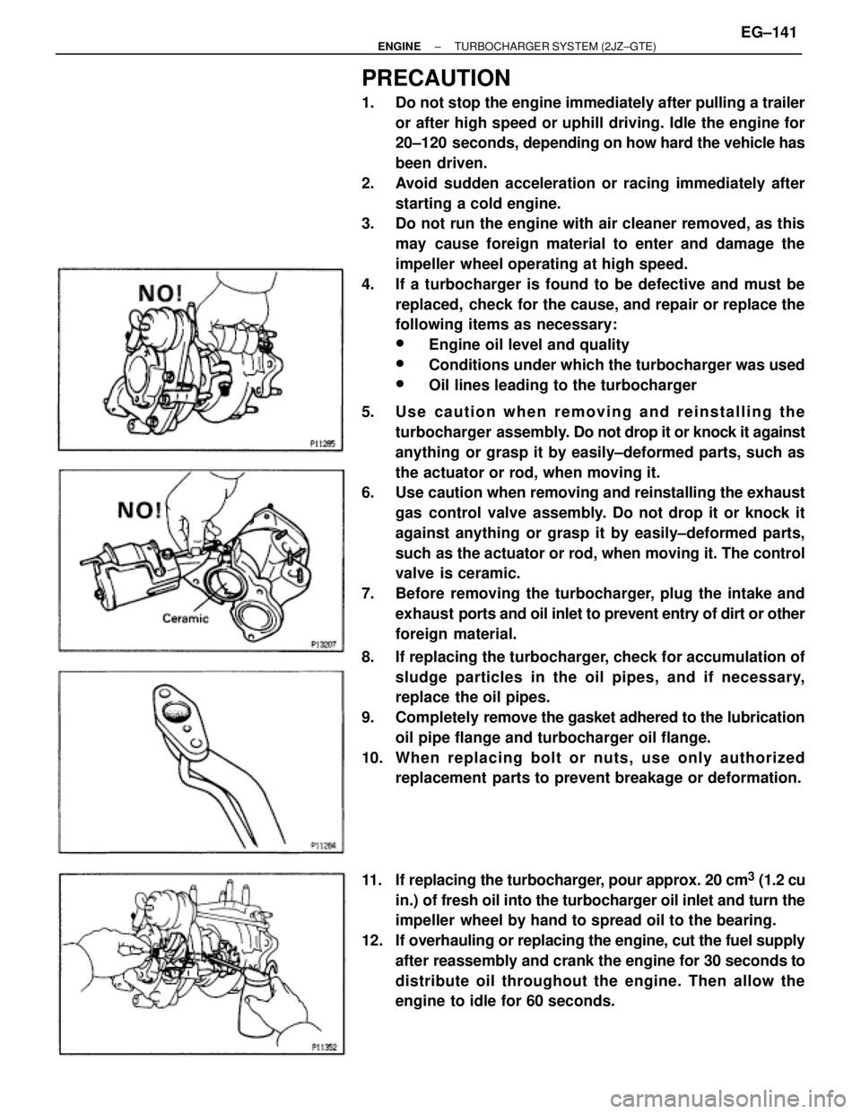
5. Use caution when removing and reinstalling the
turbocharger assembly. Do not drop it or knock it against
anything or grasp it by easily±deformed parts, such as
the actuator or rod, when moving it.
6. Use caution when removing and reinstalling the exhaust
gas control valve assembly. Do not drop it or knock it
against anything or grasp it by easily±deformed parts,
such as the actuator or rod, when moving it. The control
valve is ceramic.
7. Before removing the turbocharger, plug the intake and
exhaust ports and oil inlet to prevent entry of dirt or other
foreign material.
8. If replacing the turbocharger, check for accumulation of
sludge particles in the oil pipes, and if necessary,
replace the oil pipes.
9. Completely remove the gasket adhered to the lubrication
oil pipe flange and turbocharger oil flange.
10. Whe n re pla c ing bolt or nuts , us e only authorize d
replacement parts to prevent breakage or deformation.
11. If replacing the turbocharger, pour approx. 20 cm
3 (1.2 cu
in.) of fresh oil into the turbocharger oil inlet and turn the
impeller wheel by hand to spread oil to the bearing.
12. If overhauling or replacing the engine, cut the fuel supply
after reassembly and crank the engine for 30 seconds to
distribute oil throughout the engine. Then allow the
engine to idle for 60 seconds.
± ENGINETURBOCHARGER SYSTEM (2JZ±GTE)EG±141