Page 416 of 2543
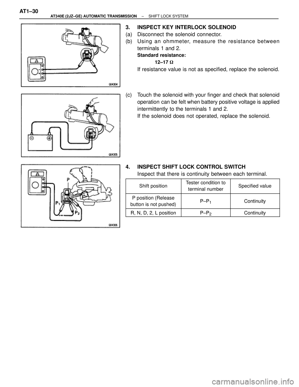
3. INSPECT KEY INTERLOCK SOLENOID
(a) Disconnect the solenoid connector.
(b) Usin g an oh mme te r, me a su re th e re sista n ce be twe e n
terminals 1 and 2.
Standard resistance:
12±17 �
If resistance value is not as specified, replace the solenoid.
(c) Touch the solenoid with your finger and check that solenoid
operation can be felt when battery positive voltage is applied
intermittently to the terminals 1 and 2.
If the solenoid does not operated, replace the solenoid.
4. INSPECT SHIFT LOCK CONTROL SWITCH
Inspect that there is continuity between each terminal.
��������� �
�������� ���������Shift position
������� �
������ �������Tester condition to
terminal number�������� �
������� ��������Specified value
��������� ���������P position (ReleasePPContinuity��������� ���������P osition (Release
button is not pushed)P±P1Continuity
��������� ���������RND2LpositionPPContinuity���������R, N, D, 2, L positionP±P2Continuity
AT1±30± AT340E (2JZ±GE) AUTOMATIC TRANSMISSIONSHIFT LOCK SYSTEM
Page 514 of 2543
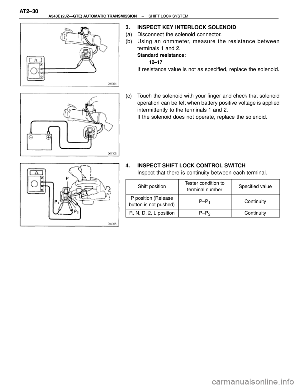
3. INSPECT KEY INTERLOCK SOLENOID
(a) Disconnect the solenoid connector.
(b) Usin g an oh mme te r, me a su re th e re sista n ce be twe e n
terminals 1 and 2.
Standard resistance:
12±17 �
If resistance value is not as specified, replace the solenoid.
(c) Touch the solenoid with your finger and check that solenoid
operation can be felt when battery positive voltage is applied
intermittently to the terminals 1 and 2.
If the solenoid does not operate, replace the solenoid.
4. INSPECT SHIFT LOCK CONTROL SWITCH
Inspect that there is continuity between each terminal.
�������� �
������� ��������Shift position
�������� �
������� ��������Tester condition to
terminal number�������� �
������� ��������Specified value
�������� �
������� ��������P position (Release
button is not pushed)�������� �
������� ��������P±P1
�������� �
������� ��������Continuity
�������� ��������R, N, D, 2, L position�������� ��������P±P2
�������� ��������Continuity
AT2±30± A340E (2JZÐGTE) AUTOMATIC TRANSMISSIONSHIFT LOCK SYSTEM
Page 611 of 2543
KEY UNLOCK WARNING INSPECTION
1. INSPECT INTEGRATION RELAY OPERATION
(a) Connect the positive (+) lead from the battery to terminal 1,
the negative (±) lead to terminals 5 and 10.
(b) Check that the buzzer sounds when the negative (±) lead
from the battery is connected to terminal 6.
If operation is not as specified, replace the relay.
2. INSPECT RELAY CIRCUIT
See page BE±18
± BODY ELECTRICAL SYSTEMIGNITION SWITCHBE±9
Page 631 of 2543
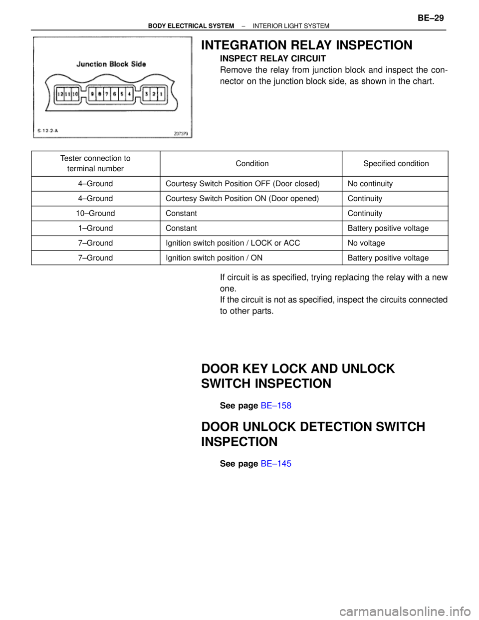
INTEGRATION RELAY INSPECTION
INSPECT RELAY CIRCUIT
Remove the relay from junction block and inspect the con-
nector on the junction block side, as shown in the chart.
������������ �
����������� ������������Tester connection to
terminal number���������������� �
��������������� ����������������Condition
���������� �
��������� ����������Specified condition
������������ ������������4±Ground���������������� ����������������Courtesy Switch Position OFF (Door closed)���������� ����������No continuity������������ �
����������� ������������4±Ground
���������������� �
��������������� ����������������Courtesy Switch Position ON (Door opened)
���������� �
��������� ����������Continuity
������������ ������������10±Ground���������������� ����������������Constant���������� ����������Continuity
������������ ������������1±Ground���������������� ����������������Constant���������� ����������Battery positive voltage
������������ ������������7±Ground���������������� ����������������Ignition switch position / LOCK or ACC���������� ����������No voltage������������ �
����������� ������������7±Ground
���������������� �
��������������� ����������������Ignition switch position / ON
���������� �
��������� ����������Battery positive voltage
If circuit is as specified, trying replacing the relay with a new
one.
If the circuit is not as specified, inspect the circuits connected
to other parts.
DOOR KEY LOCK AND UNLOCK
SWITCH INSPECTION
See page BE±158
DOOR UNLOCK DETECTION SWITCH
INSPECTION
See page BE±145
± BODY ELECTRICAL SYSTEMINTERIOR LIGHT SYSTEMBE±29
Page 657 of 2543
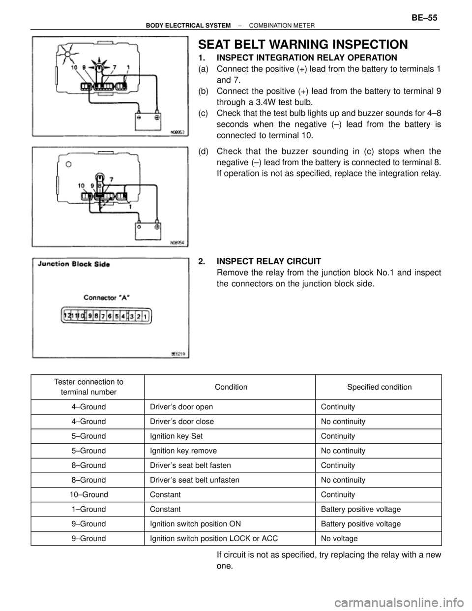
SEAT BELT WARNING INSPECTION
1. INSPECT INTEGRATION RELAY OPERATION
(a) Connect the positive (+) lead from the battery to terminals 1
and 7.
(b) Connect the positive (+) lead from the battery to terminal 9
through a 3.4W test bulb.
(c) Check that the test bulb lights up and buzzer sounds for 4±8
seconds when the negative (±) lead from the battery is
connected to terminal 10.
(d) Check that the buzzer sounding in (c) stops when the
negative (±) lead from the battery is connected to terminal 8.
If operation is not as specified, replace the integration relay.
2. INSPECT RELAY CIRCUIT
Remove the relay from the junction block No.1 and inspect
the connectors on the junction block side.
����������� �
���������� �����������Tester connection to
terminal number��������������� �
�������������� ���������������Condition
������������ �
����������� ������������Specified condition
����������� �����������4±Ground��������������� ���������������Driver's door open������������ ������������Continuity����������� �
���������� �����������4±Ground
��������������� �
�������������� ���������������Driver's door close
������������ �
����������� ������������No continuity
����������� �����������5±Ground��������������� ���������������Ignition key Set������������ ������������Continuity
����������� �����������5±Ground��������������� ���������������Ignition key remove������������ ������������No continuity
����������� �����������8±Ground��������������� ���������������Driver's seat belt fasten������������ ������������Continuity����������� �
���������� �����������8±Ground
��������������� �
�������������� ���������������Driver's seat belt unfasten
������������ �
����������� ������������No continuity
����������� �����������10±Ground��������������� ���������������Constant������������ ������������Continuity
����������� �����������1±Ground��������������� ���������������Constant������������ ������������Battery positive voltage
����������� �����������9±Ground��������������� ���������������Ignition switch position ON������������ ������������Battery positive voltage����������� �
���������� �����������9±Ground
��������������� �
�������������� ���������������Ignition switch position LOCK or ACC
������������ �
����������� ������������No voltage
If circuit is not as specified, try replacing the relay with a new
one.
± BODY ELECTRICAL SYSTEMCOMBINATION METERBE±55
Page 745 of 2543
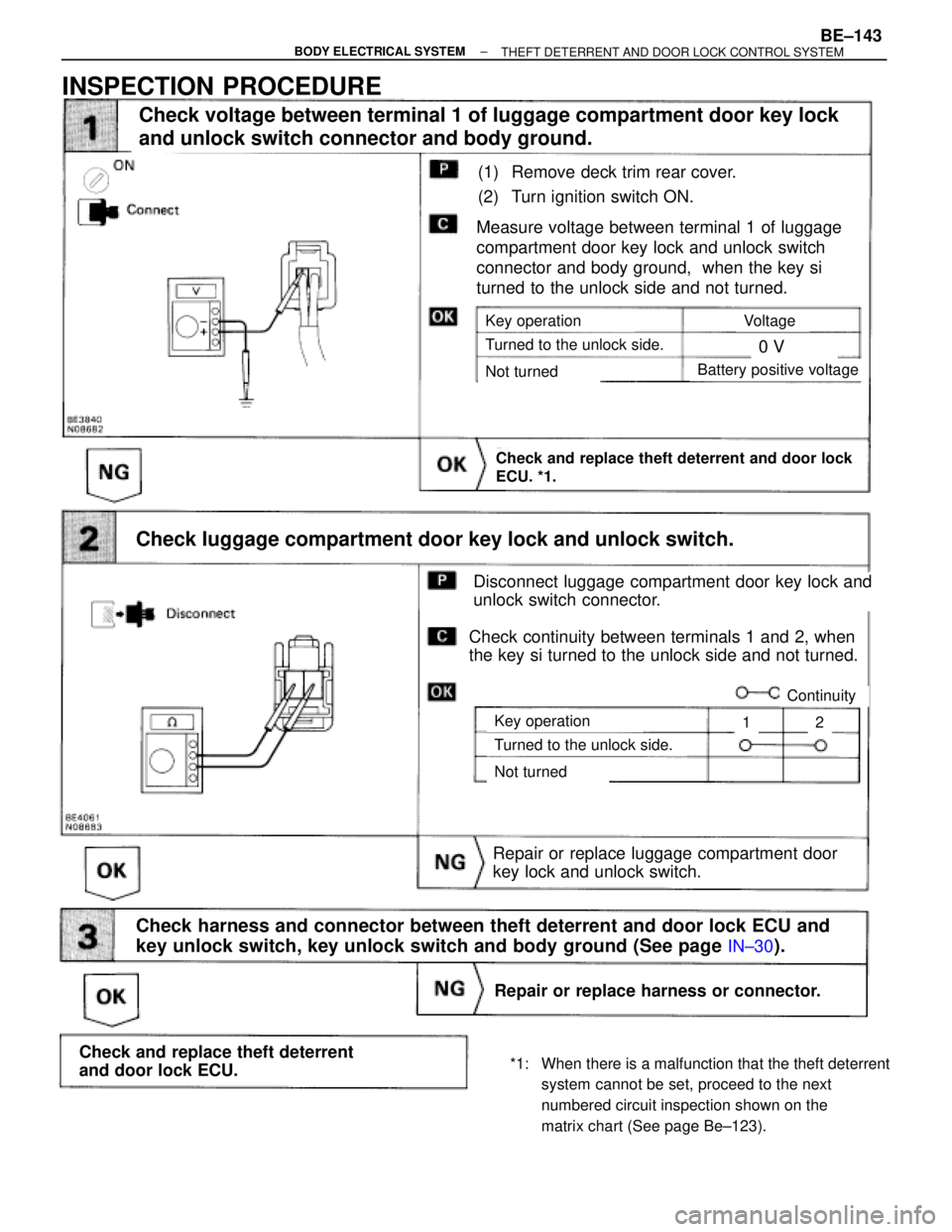
(See page IN±30).
(1) Remove deck trim rear cover.
(2) Turn ignition switch ON.
Repair or replace luggage compartment door
key lock and unlock switch.
Measure voltage between terminal 1 of luggage
compartment door key lock and unlock switch
connector and body ground, when the key si
turned to the unlock side and not turned.
Check and replace theft deterrent and door lock
ECU. *1.
Check harness and connector between theft deterrent and door lock ECU and
key unlock switch, key unlock switch and body ground (See page
IN±30).
Check voltage between terminal 1 of luggage compartment door key lock
and unlock switch connector and body ground.
Key operation
Turned to the unlock side.
Not turned
Voltage
0 V
Battery positive voltage
Check luggage compartment door key lock and unlock switch.
Key operation
Turned to the unlock side.
Not turned
Disconnect luggage compartment door key lock and
unlock switch connector.
Check continuity between terminals 1 and 2, when
the key si turned to the unlock side and not turned.
Continuity
12
Repair or replace harness or connector.
Check and replace theft deterrent
and door lock ECU.
INSPECTION PROCEDURE
*1: When there is a malfunction that the theft deterrent
system cannot be set, proceed to the next
numbered circuit inspection shown on the
matrix chart (See page Be±123).
± BODY ELECTRICAL SYSTEMBE±143THEFT DETERRENT AND DOOR LOCK CONTROL SYSTEM