Page 6 of 2543

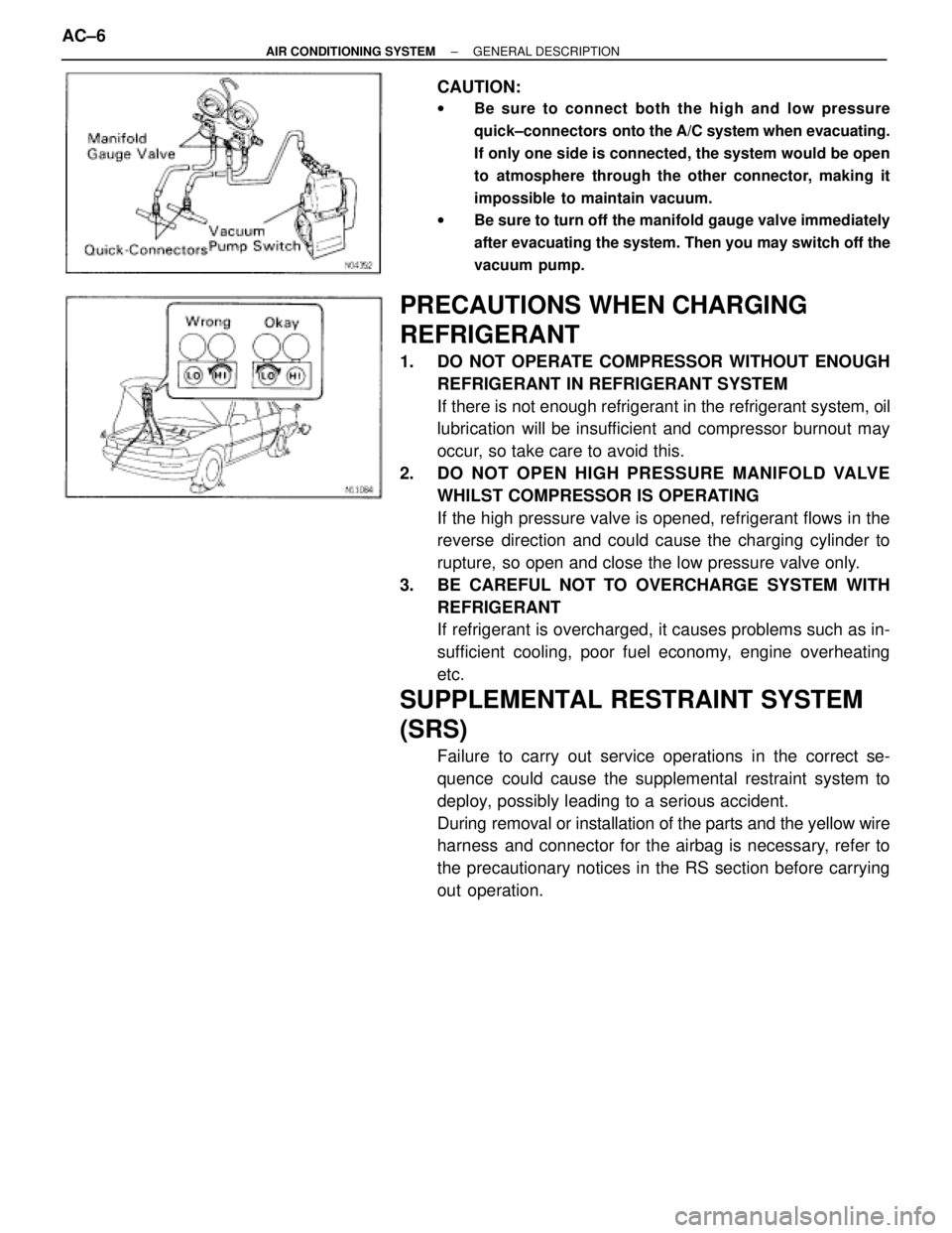
CAUTION:
wBe sure to connect both the high and low pressure
quick±connectors onto the A/C system when evacuating.
If only one side is connected, the system would be open
to atmosphere through the other connector, making it
impossible to maintain vacuum.
wBe sure to turn off the manifold gauge valve immediately
after evacuating the system. Then you may switch off the
vacuum pump.
PRECAUTIONS WHEN CHARGING
REFRIGERANT
1. DO NOT OPERATE COMPRESSOR WITHOUT ENOUGH
REFRIGERANT IN REFRIGERANT SYSTEM
If there is not enough refrigerant in the refrigerant system, oil
lubrication will be insufficient and compressor burnout may
occur, so take care to avoid this.
2. DO NOT OPEN HIGH PRESSURE MANIFOLD VALVE
WHILST COMPRESSOR IS OPERATING
If the high pressure valve is opened, refrigerant flows in the
reverse direction and could cause the charging cylinder to
rupture, so open and close the low pressure valve only.
3. BE CAREFUL NOT TO OVERCHARGE SYSTEM WITH
REFRIGERANT
If refrigerant is overcharged, it causes problems such as in-
sufficient cooling, poor fuel economy, engine overheating
etc.
SUPPLEMENTAL RESTRAINT SYSTEM
(SRS)
Failure to carry out service operations in the correct se-
quence could cause the supplemental restraint system to
deploy, possibly leading to a serious accident.
During removal or installation of the parts and the yellow wire
harness and connector for the airbag is necessary, refer to
the precautionary notices in the RS section before carrying
out operation. AC±6
± AIR CONDITIONING SYSTEMGENERAL DESCRIPTION
Page 74 of 2543

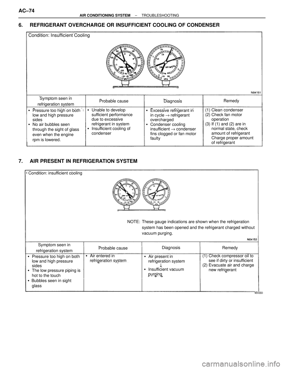
6. REFRIGERANT OVERCHARGE OR INSUFFICIENT COOLING OF CONDENSER
Symptom seen in
refrigeration systemProbable causeDiagnosisRemedy
(1) Clean condenser
(2) Check fan motor
operation
(3) If (1) and (2) are in
normal state, check
amount of refrigerant
Charge proper amount
of refrigerant�Pressure too high on both
low and high pressure
sides
�No air bubbles seen
through the sight of glass
even when the engine
rpm is lowered.�Unable to develop
sufficient performance
due to excessive
refrigerant in system
�Insufficient cooling of
condenser�Excessive refrigerant in
in cycle " refrigerant
overcharged
�Condenser cooling
insufficient " condenser
fins clogged or fan motor
faulty
Condition: Insufficient Cooling
7. AIR PRESENT IN REFRIGERATION SYSTEM
Condition: insufficient cooling
Symptom seen in
refrigeration systemProbable causeDiagnosisRemedy
(1) Check compressor oil to
see if dirty or insufficient
(2) Evacuate air and charge
new refrigerant�Pressure too high on both
low and high pressure
sides
�The low pressure piping is
hot to the touch
�Bubbles seen in sight
glass�Air entered in
refrigeration system�Air present in
refrigeration system
NOTE: These gauge indications are shown when the refrigeration
system has been opened and the refrigerant charged without
vacuum purging.
�Insufficient vacuum
purging
AC±74± AIR CONDITIONING SYSTEMTROUBLESHOOTING
Page 80 of 2543

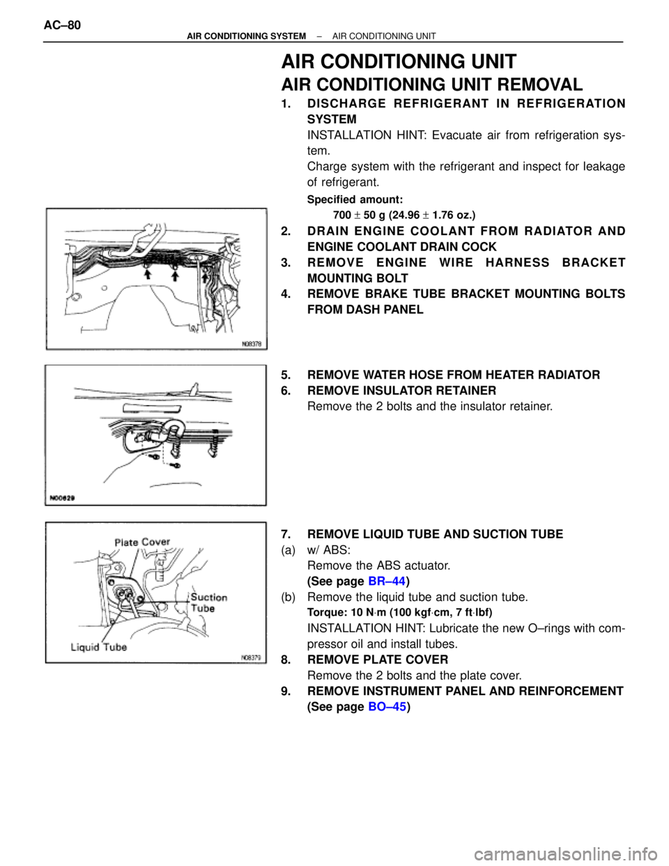
AIR CONDITIONING UNIT
AIR CONDITIONING UNIT REMOVAL
1. DISCHARGE REFRIGERANT IN REFRIGERATION
SYSTEM
INSTALLATION HINT: Evacuate air from refrigeration sys-
tem.
Charge system with the refrigerant and inspect for leakage
of refrigerant.
Specified amount:
700 + 50 g (24.96 + 1.76 oz.)
2. DRAIN ENGINE COOLANT FROM RADIATOR AND
ENGINE COOLANT DRAIN COCK
3. REMOVE ENGINE WIRE HARNESS BRACKET
MOUNTING BOLT
4. REMOVE BRAKE TUBE BRACKET MOUNTING BOLTS
FROM DASH PANEL
5. REMOVE WATER HOSE FROM HEATER RADIATOR
6. REMOVE INSULATOR RETAINER
Remove the 2 bolts and the insulator retainer.
7. REMOVE LIQUID TUBE AND SUCTION TUBE
(a) w/ ABS:
Remove the ABS actuator.
(See page BR±44)
(b) Remove the liquid tube and suction tube.
Torque: 10 NVm (100 kgfVcm, 7 ftVlbf)
INSTALLATION HINT: Lubricate the new O±rings with com-
pressor oil and install tubes.
8. REMOVE PLATE COVER
Remove the 2 bolts and the plate cover.
9. REMOVE INSTRUMENT PANEL AND REINFORCEMENT
(See page BO±45) AC±80
± AIR CONDITIONING SYSTEMAIR CONDITIONING UNIT
Page 93 of 2543
9. REMOVE LIQUID TUBE AND DISCHARGE TUBE
Torque: 10 NVm (100 kgfVcm, 7 ftVlbf)
REMOVAL NOTICE: Cap the open fittings immediately to
keep moisture out of the system.
INSTALLATION HINT: Lubricate the new O±rings with com-
pressor oil and install the tubes.
10. REMOVE CONDENSER
(a) Remove the radiator upper mounting.
(b) Push the radiator to engine side.
(c) Remove the condenser upper mounting.
(d) Push the condenser to engine side and remove the liquid
tube piping clamp.
Torque: 4.1 NVm (42 kgfVcm, 36 in.Vlbf)
± AIR CONDITIONING SYSTEMCONDENSERAC±93
Page 94 of 2543
(e) Push the condenser to engine side and pull it upward.
INSTALLATION HINT: If condenser was replaced, add com-
pressor oil to the compressor.
Add 40 cc (1.4 fl.oz.)
Compressor oil:
ND±OIL 8 or equivalent
CONDENSER INSTALLATION
Installation is in the reverse order of removal. AC±94
± AIR CONDITIONING SYSTEMCONDENSER
Page 98 of 2543
EXPANSION VALVE
ON±VEHICLE INSPECTION
1. CHECK QUANTITY OF GAS DURING REFRIGERATION
CYCLE
2. INSTALL MANIFOLD GAUGE SET
3. RUN ENGINE
Run the engine at 1,500 rpm for at least 5 minutes. Then
check that the high pressure reading is 1.371.57 MPa (14±16
kgf/cm
2, 199±228 psi).
4. CHECK EXPANSION VALVE
If the expansion valve is faulty, the low pressure reading will
drop to 0 kPa (0 kgf/cm
2, 0 psi).
HINT: When the low pressure drops to 0 kPa (0 kgf/cm
2, 0
psi), feel the receiver's IN and OUT sides for zero tempera-
ture difference.
EXPANSION VALVE REMOVAL
1. REMOVE EVAPORATOR
(See page AC±82)
2. REMOVE EXPANSION VALVE
Using a hexagon wrench, remove the 2 bolts and separate
the evaporator and expansion valve.
Torque: 5.4 NVm (55 kgfVcm, 48 in.Vlbf)
INSTALLATION HINT: Lubricate the new O±ring with com-
pressor oil and install the tubes.
EXPANSION VALVE INSTALLATION
Installation is in the reverse order of removal. AC±98
± AIR CONDITIONING SYSTEMEXPANSION VALVE
Page 132 of 2543

A340E (2JZ-GTE) AUTOMATIC TRANSMISSIONSERVICE SPECIFICATIONS -
AT-26
TORQUE SPECIFICATIONS
Part tightenedN´mkgf´cmft´lbf
Engine x Transmissin6465047
Rear support member x Body2526019
Transmission housing x Transmisson case 14 mm
17 mm34
57345
58025
42
Extension housing x Transmission case3434525
Packing lock pawl bracket77565 in.´lbf
O/D support x Transmission case2526019
Oil pump x Transmission case2121516
Oil pump body x Stator shaft101007
Valve body x Transmission case101007
Upper valve body x Lower valve body6.56556 in.´lbf
Detent spring101007
Oil strainer101007
Oil pan77565 in.´lbf
No. 1 Vehicle speed sensor1616012
No. 2 Vehicle speed sensor5.45548 in.´lbf
Solenoid wiring stopper plate5.45548 in.´lbf
O/D direct clutch vehicle speed sensor5.45548 in.´lbf
Transmission output flange123125090
Throttle cable x Transmission case5.45548 in.´lbf
Union2930022
Cooler pipe union nut3435025
Park/Neutral position switch Bolt
Nut13
6.9130
709
61 in.´lbf
Control shaft lever1616012
AT0F1-05
Page 265 of 2543

A340E(Others) AUTOMATIC TRANSMISSIONOPERATION -
AT-8
3. HYDRAULIC CONTROL SYSTEM
The hydraulic control system is composed of the oil pump, the valve body, the solenoid valves, and the
clutches and brakes, as well as the fluid passages which connect all of these components. Based on
the hydraulic pressure created by the oil pump, the hydraulic control system governs the hydraulic pres-
sure acting on the torque converter clutch, clutches and brakes in accordance with the vehicle driving
conditions.
There are 3 solenoid valves on the valve body.
The No.1 and No.2 solenoid valves are turned on and off by signals from the ECM to operate the shift
valves and change the gear shift position.
The lock-up solenoid valve is operated by signals from the ECM to engage or disengage the lock-up
clutch of the torque converter clutch.
�LINE PRESSURE
Line pressure is the most basic and important pressure used in the automatic transmission, because
it is used to operate all of the clutches and brakes in the transmission.
If the primary regulator valve does not operate correctly, line pressure will be either too high or too low.
Line pressure that is too high will lead to shifting shock and consequent engine power loss due to the
greater effort required of the oil pump; line pressure that is too low will cause slippage of clutches and
brakes, which will, in extreme cases, prevent the vehicle from moving. Therefore, if either of these prob-
lems are noted, the line pressure should be measured to see if it is within specification.
�THROTTLE PRESSURE
Throttle pressure is always kept in accordance with the opening angle of the engine throttle valve. This
throttle pressure acts on the primary regulator valve and, the line pressure is regulated according to
the throttle valve opening.
In the hydraulically controlled automatic transmission, throttle pressure is used for regulating line pres-
sure and as signal pressure for up-shift and down-shift of the transmission. In the electronically con-
trolled transmission, however, throttle pressure is used only for regulating line pressure. Consequently,
improper adjustment of the transmission throttle cable may result in a line pressure that is too high or
too low. This, in turn, will lead to shifting shock or clutch and brake slippage.