Page 653 of 2543

LOW OIL PRESSURE WARNING
INSPECTION
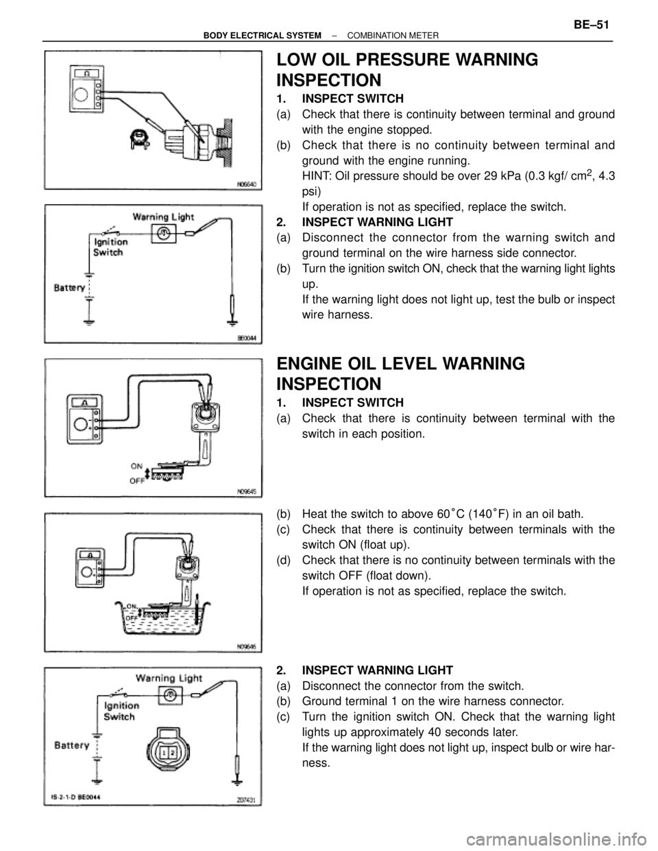
1. INSPECT SWITCH
(a) Check that there is continuity between terminal and ground
with the engine stopped.
(b) Check that there is no continuity between terminal and
ground with the engine running.
HINT: Oil pressure should be over 29 kPa (0.3 kgf/ cm
2, 4.3
psi)
If operation is not as specified, replace the switch.
2. INSPECT WARNING LIGHT
(a) Disconnect the connector from the warning switch and
ground terminal on the wire harness side connector.
(b) Turn the ignition switch ON, check that the warning light lights
up.
If the warning light does not light up, test the bulb or inspect
wire harness.
ENGINE OIL LEVEL WARNING
INSPECTION
1. INSPECT SWITCH
(a) Check that there is continuity between terminal with the
switch in each position.
(b) Heat the switch to above 60°C (140°F) in an oil bath.
(c) Check that there is continuity between terminals with the
switch ON (float up).
(d) Check that there is no continuity between terminals with the
switch OFF (float down).
If operation is not as specified, replace the switch.
2. INSPECT WARNING LIGHT
(a) Disconnect the connector from the switch.
(b) Ground terminal 1 on the wire harness connector.
(c) Turn the ignition switch ON. Check that the warning light
lights up approximately 40 seconds later.
If the warning light does not light up, inspect bulb or wire har-
ness.
± BODY ELECTRICAL SYSTEMCOMBINATION METERBE±51
Page 1045 of 2543
GENERATOR REMOVAL
Installation is in the reverse order of removal.
1. REMOVE ENGINE UNDER COVER
2. 2JZ±GTE:
REMOVE NO.2 AIR TUBE FOR CAC
3. REMOVE NO.2 FAN SHROUD
4. 2JZ±GTE M/T:
REMOVE DRIVE BELT TENSIONER DAMPER
Torque: 20 NVm (200 kgfVcm, 14 ftVlbf)
5. REMOVE DRIVE BELT
6. REMOVE GENERATOR
(a) Disconnect the generator connector.
(b) Re mo ve th e rubber cap and nut, and disconnect the
generator wire.
(c) Disconnect the generator wire clamp from the wire clip on the
generator.
(d) A/T:
Remove the bolt and pipe clamp, and disconnect the 2 oil
cooler pipes from the generator.
(e) Remove the bolt, nut, pipe bracket and generator.
Torque: 37 NVm (380 kgfVcm, 27 ftVlbf)
CH±8± CHARGING SYSTEMGENERATOR
Page 1060 of 2543

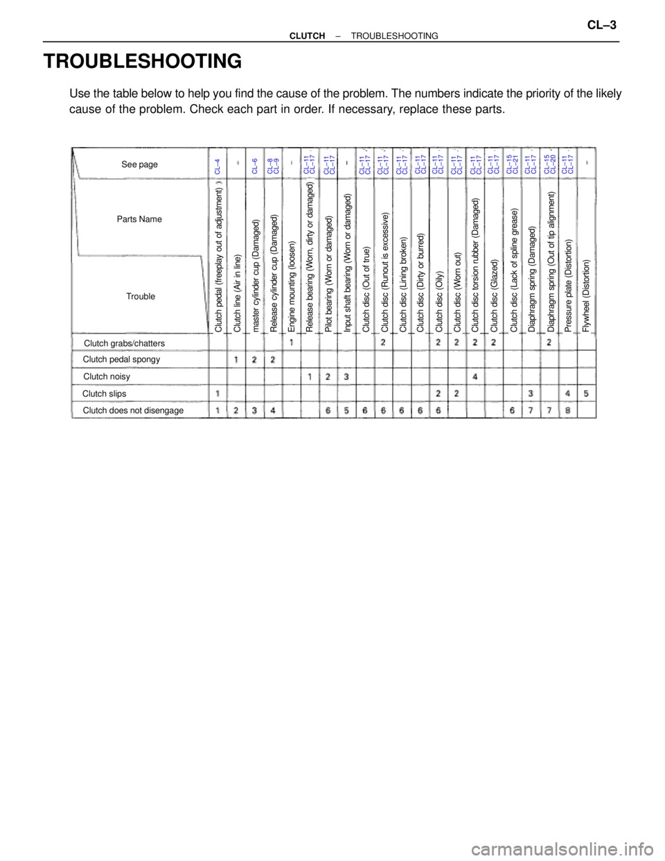
TROUBLESHOOTING
Use the table below to help you find the cause of the problem. The numbers indicate the priority of the likely
cause of the problem. Check each part in order. If necessary, replace these parts.
CL±4CL±6CL±11See page
Parts Name
Trouble
Clutch grabs/chatters
Clutch noisy
Clutch slips
Clutch pedal spongy
Clutch does not disengage
Clutch pedal (freeplay out of adjustment)Pilot bearing (Worn or damaged)Release bearing (Worn, dirty or damaged)Engine mounting (loosen)Release cylinder cup (Damaged)master cylinder cup (Damaged)Clutch line (Air in line)Clutch disc (Dirty or burred)Clutch disc (Oily)Clutch disc (Worn out)Clutch disc torsion rubber (Damaged)Clutch disc (Out of true)Input shaft bearing (Worn or damaged)Clutch disc (Lining broken)Clutch disc (Runout is excessive)Clutch disc (Lack of spline grease)Diaphragm spring (Damaged)Clutch disc (Glazed)Diaphragm spring (Out of tip alignment)Pressure plate (Distortion)Flywheel (Distortion)
CL±17CL±8CL±9CL±11CL±17CL±11CL±17CL±11CL±17CL±11CL±17CL±11CL±17CL±11CL±17CL±11CL±17CL±11CL±17CL±11CL±17CL±15CL±21CL±11CL±17CL±15CL±20CL±11CL±17
± CLUTCHTROUBLESHOOTINGCL±3
Page 1068 of 2543
CLUTCH UNIT (2JZ±GTE)
COMPONENTS
CLUTCH UNIT REMOVAL
1. REMOVE TRANSMISSION FROM ENGINE
(See page MT2±5)
HINT: Do not drain the transmission oil.
2. REMOVE RELEASE FORK ASSEMBLY
(a) Remove the release fork assembly from the left side of clutch
housing service hole.
(b) Remove the E±ring from the release fork.
(c) Remove the pin and wave washer from the release fork.
± CLUTCHCLUTCH RELEASE CYLINDER(2JZ±GTE)CL±11
Page 1075 of 2543

CLUTCH UNIT REMOVAL
1. REMOVE TRANSMISSION FROM ENGINE
(See page MT1±8)
HINT: Do not drain the transmission oil.
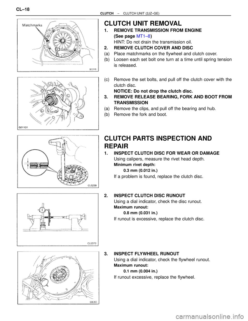
2. REMOVE CLUTCH COVER AND DISC
(a) Place matchmarks on the flywheel and clutch cover.
(b) Loosen each set bolt one turn at a time until spring tension
is released.
(c) Remove the set bolts, and pull off the clutch cover with the
clutch disc.
NOTICE: Do not drop the clutch disc.
3. REMOVE RELEASE BEARING, FORK AND BOOT FROM
TRANSMISSION
(a) Remove the clips, and pull off the bearing and hub.
(b) Remove the fork and boot.
CLUTCH PARTS INSPECTION AND
REPAIR
1. INSPECT CLUTCH DISC FOR WEAR OR DAMAGE
Using calipers, measure the rivet head depth.
Minimum rivet depth:
0.3 mm (0.012 in.)
If a problem is found, replace the clutch disc.
2. INSPECT CLUTCH DISC RUNOUT
Using a dial indicator, check the disc runout.
Maximum runout:
0.8 mm (0.031 in.)
If runout is excessive, replace the clutch disc.
3. INSPECT FLYWHEEL RUNOUT
Using a dial indicator, check the flywheel runout.
Maximum runout:
0.1 mm (0.004 in.)
If runout excessive, replace the flywheel. CL±18
± CLUTCHCLUTCH UNIT (2JZ±GE)
Page 1081 of 2543
COOLANT CHECK
1. CHECK ENGINE COOLANT LEVEL AT RADIATOR
RESERVOIR
The engine coolant level should be between the ºLOWº and
ºFULLº lines.
If low, check for leaks and add engine coolant up to the
ºFULLº line.
2. CHECK ENGINE COOLANT QUALITY
(a) Remove the radiator cap.
CAUTION: To avoid the danger of being burned, do not remove
the radiator cap while the engine and radiator are still hot, as
fluid and steam can be blown out under pressure.
(b) There should not be any excessive deposits of rust or scale
around the radiator cap or radiator filler hole, and the coolant
should be free from oil.
If excessively dirty, replace the coolant.
(c) Reinstall the radiator cap. EG±330
± ENGINECOOLING SYSTEM
Page 1088 of 2543

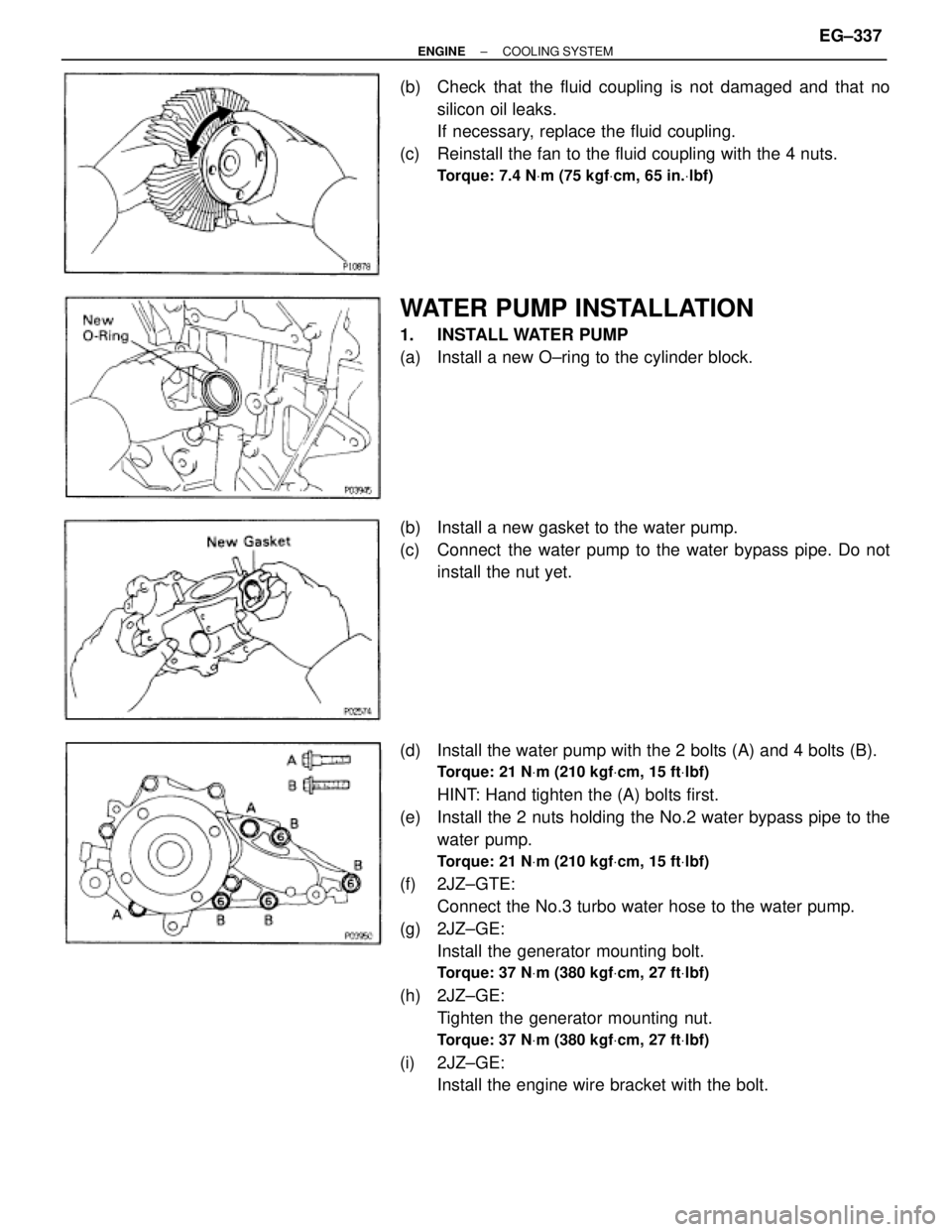
(b) Check that the fluid coupling is not damaged and that no
silicon oil leaks.
If necessary, replace the fluid coupling.
(c) Reinstall the fan to the fluid coupling with the 4 nuts.
Torque: 7.4 NVm (75 kgfVcm, 65 in.Vlbf)
WATER PUMP INSTALLATION
1. INSTALL WATER PUMP
(a) Install a new O±ring to the cylinder block.
(b) Install a new gasket to the water pump.
(c) Connect the water pump to the water bypass pipe. Do not
install the nut yet.
(d) Install the water pump with the 2 bolts (A) and 4 bolts (B).
Torque: 21 NVm (210 kgfVcm, 15 ftVlbf)
HINT: Hand tighten the (A) bolts first.
(e) Install the 2 nuts holding the No.2 water bypass pipe to the
water pump.
Torque: 21 NVm (210 kgfVcm, 15 ftVlbf)
(f) 2JZ±GTE:
Connect the No.3 turbo water hose to the water pump.
(g) 2JZ±GE:
Install the generator mounting bolt.
Torque: 37 NVm (380 kgfVcm, 27 ftVlbf)
(h) 2JZ±GE:
Tighten the generator mounting nut.
Torque: 37 NVm (380 kgfVcm, 27 ftVlbf)
(i) 2JZ±GE:
Install the engine wire bracket with the bolt.
± ENGINECOOLING SYSTEMEG±337
Page 1097 of 2543
RADIATOR REMOVAL
Installation is in the reverse order of removal.
1. REMOVE ENGINE UNDER COVER
INSTALLATION HINT: Start the engine, and check for cool-
ant and A/T fluid leaks.
2. REMOVE BATTERY AND BATTERY TRAY
3. DRAIN ENGINE COOLANT
4. 2JZ±GTE:
REMOVE NO.2 AIR TUBE
5. REMOVE NO.2 FAN SHROUD
(a) Remove the 2 clips.
(b) Disconnect the claw of the No.2 fan shroud from the hook of
the No.1 fan shroud, and remove the No.2 fan shroud.
6. REMOVE AIR CLEANER DUCT
7. 2JZ±GTE:
REMOVE NO.5 AIR HOSE
8. REMOVE LH HEADLIGHT BEAM ANGLE GAUGE
Remove the screw and beam angle gauge.
9. DISCONNECT HOSES FROM RADIATOR
Disconnect these hoses from the radiator:
(1) Reservoir inlet hose
(2) Upper radiator hose
(3) Lower radiator hose
(4) A/T:
2 oil cooler hoses
Plug the hose ends.
INSTALLATION HINT: Check the A/T fluid level.
(See item 21 in Maintenance) EG±346
± ENGINECOOLING SYSTEM