Page 2 of 2543
, previously used in automobiles
air conditioning systems is believed to contribute towards the
depletion the e")
GENERAL DESCRIPTION
NEW AIR CONDITIONING SYSTEM WITH
HFC134a
Refrigerant CFC 12 (R 12), previously used in automobiles'
air conditioning systems is believed to contribute towards the
depletion the earth's ozone layer. The ozone layer help to
protect us against the harmful ultraviolet rays of the sun.
A newly developed refrigerant, HFC 134a (R 134 a), does not
the destroy the ozone layer.
PRECAUTIONS FOR SERVICING
HFC134a AIR CONDITIONINGS
1. USE OF NEW REFRIGERANT HFC134a
The very different characteristics of refrigerants HFC134a
and CFC12 have determined the design of their respective
air conditioning systems. Under no circumstances allow
CFC12 to enter an HFC134a system, or vice versa, because
serious damage could occur.
2. USE OF PROPER COMPRESSOR OIL
Compressor oil used in conventional CFC12 air conditioning
systems cannot be used in HFC134a air conditioning sys-
tems.
Always use genuine Toyota R134a air conditioning oil ND±
OIL 8, made expressly for use with HFC134a.
NOTICE: Compressor oil (ND±OIL 8) for HFC134a use ad-
versely affects acrylic resin, so take care not to spill or
spray any compressor oil.
If even a small amount of the wrong oil is changed, it will result
in clouding of the refrigerant.
A large amount will cause the compressor to seize up. AC±2
± AIR CONDITIONING SYSTEMGENERAL DESCRIPTION
Page 3 of 2543

3. USE OF PROPER O±RINGS AND SEALS
O±rings and seals used for conventional CFC12 air condi-
tioning systems cannot be used for HFC134a air conditioning
systems.
Always use genuine Toyota HFC134a system O±rings and
seals for HFC134a air conditioning systems.
If O±rings and/or seals for CFC12 air conditioning systems
are used by mistake in the connections of an HFC134a air
conditioning system, the O±ring and seals will foam and swell
resulting in leakage of refrigerant.
4. TIGHTEN CONNECTING PARTS SECURELY
Securely tighten the connecting parts to prevent leaking of
refrigerant gas.
wApply a few drops of compressor oil to O±ring fittings for
easy tightening and to prevent leaking of refrigerant
gas.
CAUTION: Apply only ND±OIL 8 compressor oil.
wTighten the nuts using 2 wrenches to avoid twisting the
tube.
wTighten the O±ring fittings or the bolted type fittings to
the specified torque.
5. INSERT PLUG IMMEDIATELY IN DISCONNECTED PARTS
Insert a plug immediately in the disconnected parts to pre-
vent the ingress of moisture and dust.
6. DO NOT REMOVE PLUG FROM NEW PARTS UNTIL
IMMEDIATELY BEFORE INSTALLATION
7. DISCHARGE GAS IN NEW COMPRESSOR FROM
CHARGING VALVE BEFORE INSTALLING IT
If the gas in the new compressor is not discharged first, com-
pressor oil will spray out with gas when the plug is removed.
± AIR CONDITIONING SYSTEMGENERAL DESCRIPTIONAC±3
Page 4 of 2543

SERVICE TOOLS FOR HFC134a AIR
CONDITIONING
When servicing HFC134a air conditioning systems always
use the HFC134a dedicated manifold gauges, gas leak de-
tector and vacuum pump adaptor.
1. USE MANIFOLD GAUGES FOR HFC134a AIR
CONDITIONING
Always use HFC134a dedicated manifold gauges to prevent
CFC 12 and CFC 12 compressor oil contaminating the
HFC134a system.
2. USE HFC134a GAS LEAK DETECTOR
Similarly, always use an HFC134a dedicated leak detector.
The CFC12 leak detector is not sufficiently sensitive.
3. USE VACUUM PUMP ADAPTER
By connecting a vacuum pump adapter, the vacuum pump
can be used for both HFC134a and CFC12 air conditioning
systems.
The vacuum pump adaptor has an internal magnetic valve.
When evacuation is completed and the vacuum pump switch
is turned off, the magnetic valve opens allowing the introduc-
tion atmospheric air into the manifold gauges to prevent the
back flow of oil from the vacuum pump into the gauge hose.
CAUTION:
Be sure to turn off the manifold gauge valve immediately
after evacuating the system. Then you may switch off the
vacuum pump. If this order is reversed, the line will be
temporarily open to atmosphere. AC±4
± AIR CONDITIONING SYSTEMGENERAL DESCRIPTION
Page 6 of 2543

CAUTION:
wBe sure to connect both the high and low pressure
quick±connectors onto the A/C system when evacuating.
If only one side is connected, the system would be open
to atmosphere through the other connector, making it
impossible to maintain vacuum.
wBe sure to turn off the manifold gauge valve immediately
after evacuating the system. Then you may switch off the
vacuum pump.
PRECAUTIONS WHEN CHARGING
REFRIGERANT
1. DO NOT OPERATE COMPRESSOR WITHOUT ENOUGH
REFRIGERANT IN REFRIGERANT SYSTEM
If there is not enough refrigerant in the refrigerant system, oil
lubrication will be insufficient and compressor burnout may
occur, so take care to avoid this.
2. DO NOT OPEN HIGH PRESSURE MANIFOLD VALVE
WHILST COMPRESSOR IS OPERATING
If the high pressure valve is opened, refrigerant flows in the
reverse direction and could cause the charging cylinder to
rupture, so open and close the low pressure valve only.
3. BE CAREFUL NOT TO OVERCHARGE SYSTEM WITH
REFRIGERANT
If refrigerant is overcharged, it causes problems such as in-
sufficient cooling, poor fuel economy, engine overheating
etc.
SUPPLEMENTAL RESTRAINT SYSTEM
(SRS)
Failure to carry out service operations in the correct se-
quence could cause the supplemental restraint system to
deploy, possibly leading to a serious accident.
During removal or installation of the parts and the yellow wire
harness and connector for the airbag is necessary, refer to
the precautionary notices in the RS section before carrying
out operation. AC±6
± AIR CONDITIONING SYSTEMGENERAL DESCRIPTION
Page 10 of 2543
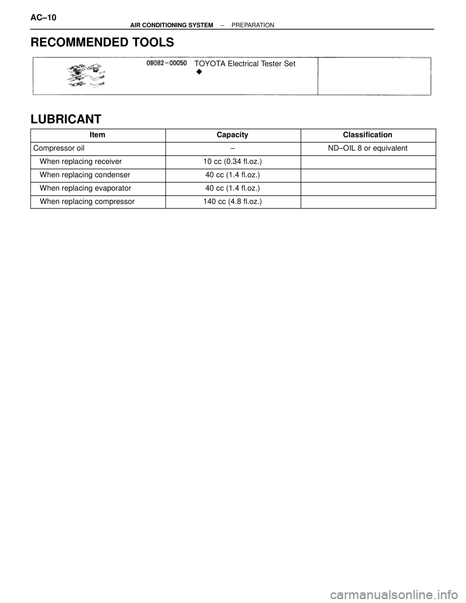
RECOMMENDED TOOLS
TOYOTA Electrical Tester Set
LUBRICANT������������� �
������������ �������������Item
������������ �
����������� ������������Capacity
������������� �
������������ �������������Classification
������������� �������������Compressor oil������������ ������������±������������� �������������ND±OIL 8 or equivalent
������������� ������������� When replacing receiver������������ ������������10 cc (0.34 fl.oz.)������������� �������������
������������� ������������� When replacing condenser������������ ������������40 cc (1.4 fl.oz.)������������� �������������
������������� ������������� When replacing evaporator������������ ������������40 cc (1.4 fl.oz.)������������� �������������
������������� ������������� When replacing compressor������������ ������������140 cc (4.8 fl.oz.)������������� �������������
AC±10± AIR CONDITIONING SYSTEMPREPARATION
Page 74 of 2543
 Clean condenser
(2) Check fan motor
operation
(3) If (1) and (2)")
6. REFRIGERANT OVERCHARGE OR INSUFFICIENT COOLING OF CONDENSER
Symptom seen in
refrigeration systemProbable causeDiagnosisRemedy
(1) Clean condenser
(2) Check fan motor
operation
(3) If (1) and (2) are in
normal state, check
amount of refrigerant
Charge proper amount
of refrigerant�Pressure too high on both
low and high pressure
sides
�No air bubbles seen
through the sight of glass
even when the engine
rpm is lowered.�Unable to develop
sufficient performance
due to excessive
refrigerant in system
�Insufficient cooling of
condenser�Excessive refrigerant in
in cycle " refrigerant
overcharged
�Condenser cooling
insufficient " condenser
fins clogged or fan motor
faulty
Condition: Insufficient Cooling
7. AIR PRESENT IN REFRIGERATION SYSTEM
Condition: insufficient cooling
Symptom seen in
refrigeration systemProbable causeDiagnosisRemedy
(1) Check compressor oil to
see if dirty or insufficient
(2) Evacuate air and charge
new refrigerant�Pressure too high on both
low and high pressure
sides
�The low pressure piping is
hot to the touch
�Bubbles seen in sight
glass�Air entered in
refrigeration system�Air present in
refrigeration system
NOTE: These gauge indications are shown when the refrigeration
system has been opened and the refrigerant charged without
vacuum purging.
�Insufficient vacuum
purging
AC±74± AIR CONDITIONING SYSTEMTROUBLESHOOTING
Page 80 of 2543

AIR CONDITIONING UNIT
AIR CONDITIONING UNIT REMOVAL
1. DISCHARGE REFRIGERANT IN REFRIGERATION
SYSTEM
INSTALLATION HINT: Evacuate air from refrigeration sys-
tem.
Charge system with the refrigerant and inspect for leakage
of refrigerant.
Specified amount:
700 + 50 g (24.96 + 1.76 oz.)
2. DRAIN ENGINE COOLANT FROM RADIATOR AND
ENGINE COOLANT DRAIN COCK
3. REMOVE ENGINE WIRE HARNESS BRACKET
MOUNTING BOLT
4. REMOVE BRAKE TUBE BRACKET MOUNTING BOLTS
FROM DASH PANEL
5. REMOVE WATER HOSE FROM HEATER RADIATOR
6. REMOVE INSULATOR RETAINER
Remove the 2 bolts and the insulator retainer.
7. REMOVE LIQUID TUBE AND SUCTION TUBE
(a) w/ ABS:
Remove the ABS actuator.
(See page BR±44)
(b) Remove the liquid tube and suction tube.
Torque: 10 NVm (100 kgfVcm, 7 ftVlbf)
INSTALLATION HINT: Lubricate the new O±rings with com-
pressor oil and install tubes.
8. REMOVE PLATE COVER
Remove the 2 bolts and the plate cover.
9. REMOVE INSTRUMENT PANEL AND REINFORCEMENT
(See page BO±45) AC±80
± AIR CONDITIONING SYSTEMAIR CONDITIONING UNIT
Page 83 of 2543
 Disconnect the connector.
(b) Disconnect the control link.
(c) Remove the 3 screws and the air inlet servomotor.
2. REMOVE BLOWER MOTOR CONTROL RELAY
(a) Disco")
1. REMOVE AIR INLET SERVOMOTOR
(a) Disconnect the connector.
(b) Disconnect the control link.
(c) Remove the 3 screws and the air inlet servomotor.
2. REMOVE BLOWER MOTOR CONTROL RELAY
(a) Disconnect the connector.
(b) Remove the 3 screws and the blower motor control relay.
3. REMOVE BLOWER MOTOR
(a) Disconnect the connector.
(b) Using a torx driver, remove the blower motor.
4. REMOVE EVAPORATOR
(a) Remove the A/C unit wire harness.
(b) Remove the foot air duct.
(c) Remove the A/C unit block joint.
(d) Remove the 6 screws and down and the lower cover.
(e) Remove the 4 screws and the evaporator cover.
(f) Pull out the evaporator.
(g) Pull out the evaporator sensor from the evaporator.
(h) Using a hexagon wrench, remove the 2 bolts and separate
the evaporator and expansion valve.
Torque: 5.4 NVm (55 kgfVcm, 48 in.Vlbf)
INSTALLATION HINT: If the evaporator was replaced, add
compressor oil to the compressor.
Add 40 cc (1.4 fl.oz)
Compressor oil
ND±OIL 8 or equivalent
± AIR CONDITIONING SYSTEMAIR CONDITIONING UNITAC±83