Page 53 of 2543
INSPECTION PROCEDURE
Remove the A/C amplifier with connector still con-
ected.
Measure voltage between terminal + B of air condi-
tioner control assembly connector and body ground.
Voltage: Battery positive voltage
Proceed to next circuit inspection shown on matrix
chart (See page AC±26).
Remove ECU±B fuse from J/B No. 1.
Check continuity of ECU±B fuse.
Continuity
Check ECU±B fuse.
Check for short in all the harness and compo-
nents to the ECU±B fuse (See attached wiring
diagram).
Check voltage between terminal +B of A/C amplifier connector and
body ground.
Check and repair harness and connector between
A/C amplifier and battery.
± AIR CONDITIONING SYSTEMTROUBLESHOOTINGAC±53
Page 57 of 2543
INSPECTION PROCEDURE
Check voltage between terminal ACC of A/C amplifier connector and
body ground.
Remove the A/C amplifier with connector still connected
Voltage: Battery positive voltage
1. Turn ignition switch To ACC.
2. Measure voltage between terminals ACC of A/C
amplifier connector and body ground.
Remove CIG fuse from J/B No. 1.
Check continuity of CIG fuse.
Continuity
Proceed to next circuit inspection shown on matrix
chart (See page AC±26).
Check CIG fuse.
Check for short in all the harness and compo-
nents to the CIG fuse (See attached wiring
diagram).
Check and repair harness and connector between
A/C amplifier and battery.
± AIR CONDITIONING SYSTEMTROUBLESHOOTINGAC±57
Page 59 of 2543
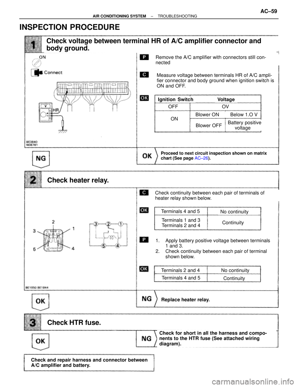
Check voltage between terminal HR of A/C amplifier connector and
body ground.
Check heater relay.
Proceed to next circuit inspection shown on matrix
chart (See page AC±26).
Check HTR fuse.
Check and repair harness and connector between
A/C amplifier and battery.
Check for short in all the harness and compo-
nents to the HTR fuse (See attached wiring
diagram).
Replace heater relay.
Remove the A/C amplifier with connectors still con-
nected
Measure voltage between terminals HR of A/C ampli-
fier connector and body ground when ignition switch is
ON and OFF.
VoltageIgnition Switch
Check continuity between each pair of terminals of
heater relay shown below.
1. Apply battery positive voltage between terminals
1 and 3.
2. Check continuity between each pair of terminal
shown below.
Terminals 2 and 4
Terminals 4 and 5
No continuity
Continuity
Terminals 4 and 5
Terminals 1 and 3
Terminals 2 and 4
No continuity
Continuity
OFF
ON
OV
Blower OFF
Blower ON Below 1.O V
Battery positive
voltage
INSPECTION PROCEDURE
± AIR CONDITIONING SYSTEMTROUBLESHOOTINGAC±59
Page 689 of 2543
������������������������������ ������������������������������Problem������� �������No.
������������ ������������Noise������������������� �������������������Noise produced by vibration or shock while driving.������� �������30
������������ ������������������������������� �������������������Noise produced when engine starts.������� �������31
������������ ������������Antenna������������������� �������������������Antenna±related.������� �������32
������������ ������������ANTI±THEFT SYSTEM������������������� �������������������Troubleshooting for ANTI±THEFT SYSTEM������� �������33
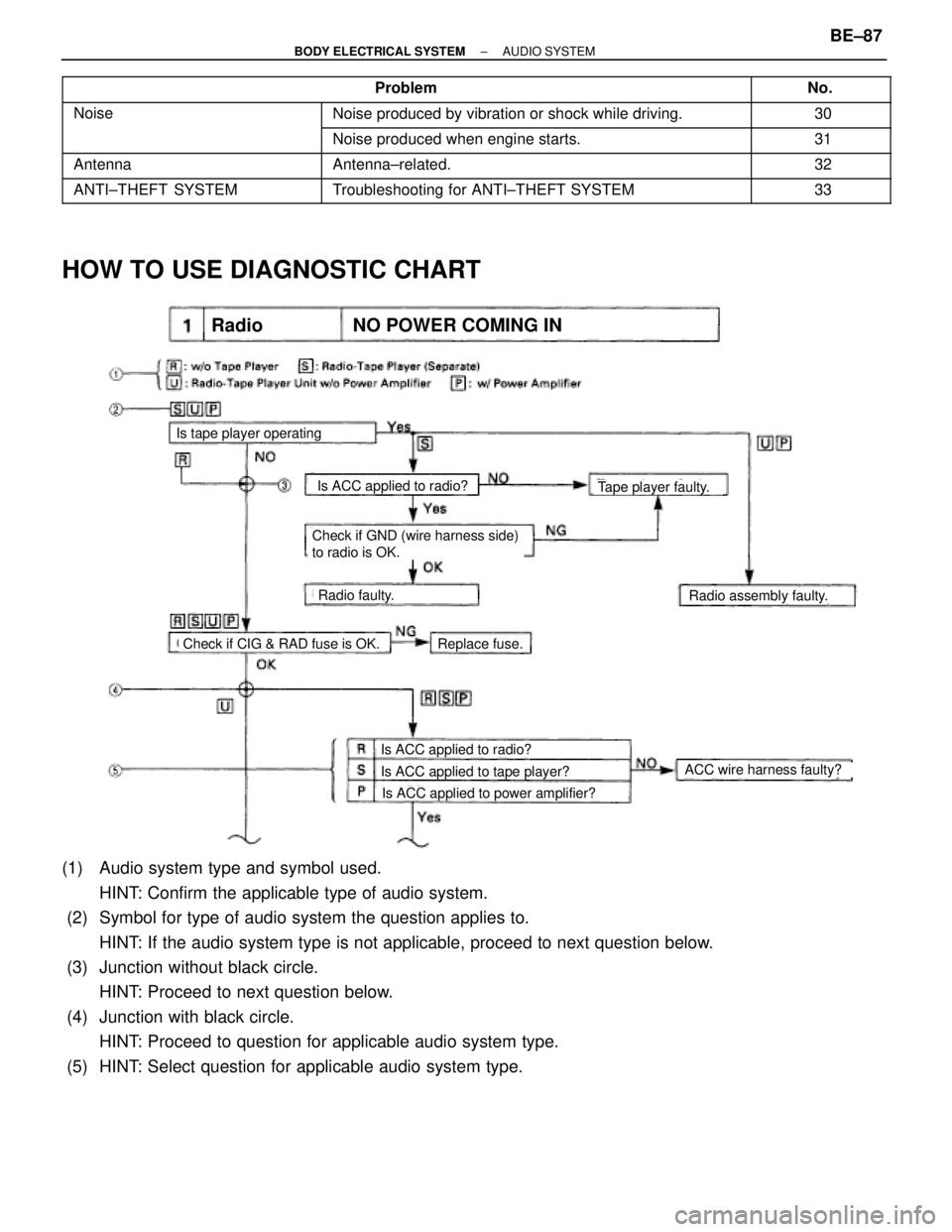
HOW TO USE DIAGNOSTIC CHART
Is tape player operating
Is ACC applied to radio?Tape player faulty.
Check if GND (wire harness side)
to radio is OK.
Radio faulty.Radio assembly faulty.
Check if CIG & RAD fuse is OK.Replace fuse.
Is ACC applied to radio?
Is ACC applied to tape player?
Is ACC applied to power amplifier?
ACC wire harness faulty?
NO POWER COMING INRadio
(1) Audio system type and symbol used.
HINT: Confirm the applicable type of audio system.
(2) Symbol for type of audio system the question applies to.
HINT: If the audio system type is not applicable, proceed to next question below.
(3) Junction without black circle.
HINT: Proceed to next question below.
(4) Junction with black circle.
HINT: Proceed to question for applicable audio system type.
(5) HINT: Select question for applicable audio system type.
± BODY ELECTRICAL SYSTEMAUDIO SYSTEMBE±87
Page 753 of 2543
(See page Be±123).
(See page IN±30).
Remove DOME fuse from R/B No. 2
Repair or replace harness or connector.
Check continuity of DOME fuse.
Continuity
Check for short in all the harness and components
connected to the DOME fuse (See attached wiring
diagram).
Proceed to next circuit inspection shown on matrix
chart (See page BE±123).
(1)Remove the No. 1 under cover and heater duct.
(2)Disconnect the theft deterrent and door lock ECU
connector.
Measure voltage between terminals +B1 and E of
ECU connector.
Check DOME fuse.
Check voltage between terminals +B1 and E of ECU connector.
Check for open in harness and connector between ECU and body ground
(See page IN±30).
Voltage: 10 ± 14 V
Check and repair harness and connector be-
tween ECU and battery.
INSPECTION PROCEDURES
± BODY ELECTRICAL SYSTEMBE±151THEFT DETERRENT AND DOOR LOCK CONTROL SYSTEM
Page 755 of 2543
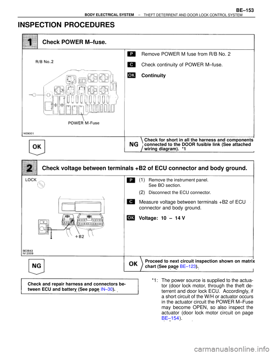
INSPECTION PROCEDURES
(See page BE±123).
page BE±154).
Remove POWER M fuse from R/B No. 2
Check continuity of POWER M±fuse.
Continuity
Check POWER M±fuse.
Check for short in all the harness and components
connected to the DOOR fusible link (See attached
wiring diagram). *1
Proceed to next circuit inspection shown on matrix
chart (See page BE±123).
(1)Remove the instrument panel.
See BO section.
(2)Disconnect the ECU connector.
Measure voltage between terminals +B2 of ECU
connector and body ground.
Check voltage between terminals +B2 of ECU connector and body ground.
Voltage: 10 ± 14 V
*1: The power source is supplied to the actua-
tor (door lock motor, through the theft de-
terrent and door lock ECU. Accordingly, if
a short circuit of the W/H or actuator occurs
in the actuator circuit the POWER M±Fuse
may become OPEN, so also inspect the
actuator (door lock motor circuit on page
BE±154).Check and repair harness and connectors be-
tween ECU and battery (See page IN±30).
± BODY ELECTRICAL SYSTEMBE±153THEFT DETERRENT AND DOOR LOCK CONTROL SYSTEM
Page 770 of 2543
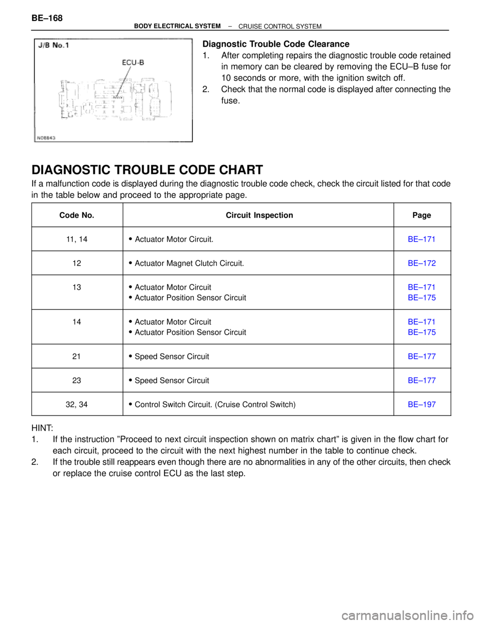
Diagnostic Trouble Code Clearance
1. After completing repairs the diagnostic trouble code retained
in memory can be cleared by removing the ECU±B fuse for
10 seconds or more, with the ignition switch off.
2. Check that the normal code is displayed after connecting the
fuse.
DIAGNOSTIC TROUBLE CODE CHART
If a malfunction code is displayed during the diagnostic trouble code check, check the circuit listed for that code
in the table below and proceed to the appropriate page.
��������� �
�������� ���������Code No.
����������������������� �
���������������������� �����������������������Circuit Inspection
������ �
����� ������Page
��������� �
�������� ���������11, 14
����������������������� �
���������������������� ������������������������ Actuator Motor Circuit.
������ �
����� ������BE±171
��������� �
�������� ���������12
����������������������� �
���������������������� ������������������������ Actuator Magnet Clutch Circuit.
������ �
����� ������BE±172
��������� �
�������� �
�������� ���������
13
����������������������� �
���������������������� �
���������������������� �����������������������
� Actuator Motor Circuit
� Actuator Position Sensor Circuit
������ �
����� �
����� ������
BE±171
BE±175
��������� �
�������� �
�������� ���������
14
����������������������� �
���������������������� �
���������������������� �����������������������
� Actuator Motor Circuit
� Actuator Position Sensor Circuit
������ �
����� �
����� ������
BE±171
BE±175
��������� �
�������� ���������21
����������������������� �
���������������������� ������������������������ Speed Sensor Circuit
������ �
����� ������BE±177
��������� �
�������� ���������23
����������������������� �
���������������������� ������������������������ Speed Sensor Circuit
������ �
����� ������BE±177
��������� �
�������� ���������32, 34����������������������� �
���������������������� ������������������������ Control Switch Circuit. (Cruise Control Switch)������ �
����� ������BE±197
HINT:
1. If the instruction ºProceed to next circuit inspection shown on matrix chartº is given in the flow chart for
each circuit, proceed to the circuit with the next highest number in the table to continue check.
2. If the trouble still reappears even though there are no abnormalities in any of the other circuits, then check
or replace the cruise control ECU as the last step. BE±168
± BODY ELECTRICAL SYSTEM
CRUISE CONTROL SYSTEM
Page 794 of 2543
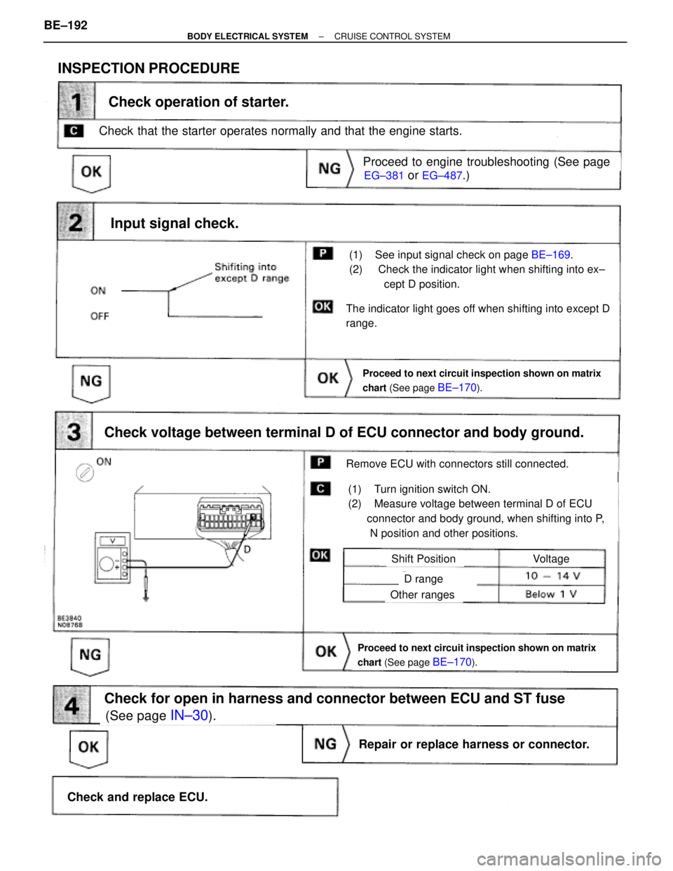
INSPECTION PROCEDURE
Check that the starter operates normally and that the engine starts.
EG±381 or EG±487.)
(See page IN±30).
on page BE±169.
Proceed to next circuit inspection shown on matrix
chart (See page
BE±170).
(1) See input signal check on page BE±169.
(2) Check the indicator light when shifting into ex±
cept D position.
Check operation of starter.
Check voltage between terminal D of ECU connector and body ground.
(1) Turn ignition switch ON.
(2) Measure voltage between terminal D of ECU
connector and body ground, when shifting into P,
N position and other positions.
Remove ECU with connectors still connected.
Input signal check.
The indicator light goes off when shifting into except D
range.
Proceed to engine troubleshooting (See page
Proceed to next circuit inspection shown on matrix
chart (See page
BE±170).
VoltageShift Position
D range
Other ranges
Check for open in harness and connector between ECU and ST fuse
Repair or replace harness or connector.
Check and replace ECU. BE±192
± BODY ELECTRICAL SYSTEMCRUISE CONTROL SYSTEM