Page 104 of 2543
SENSOR
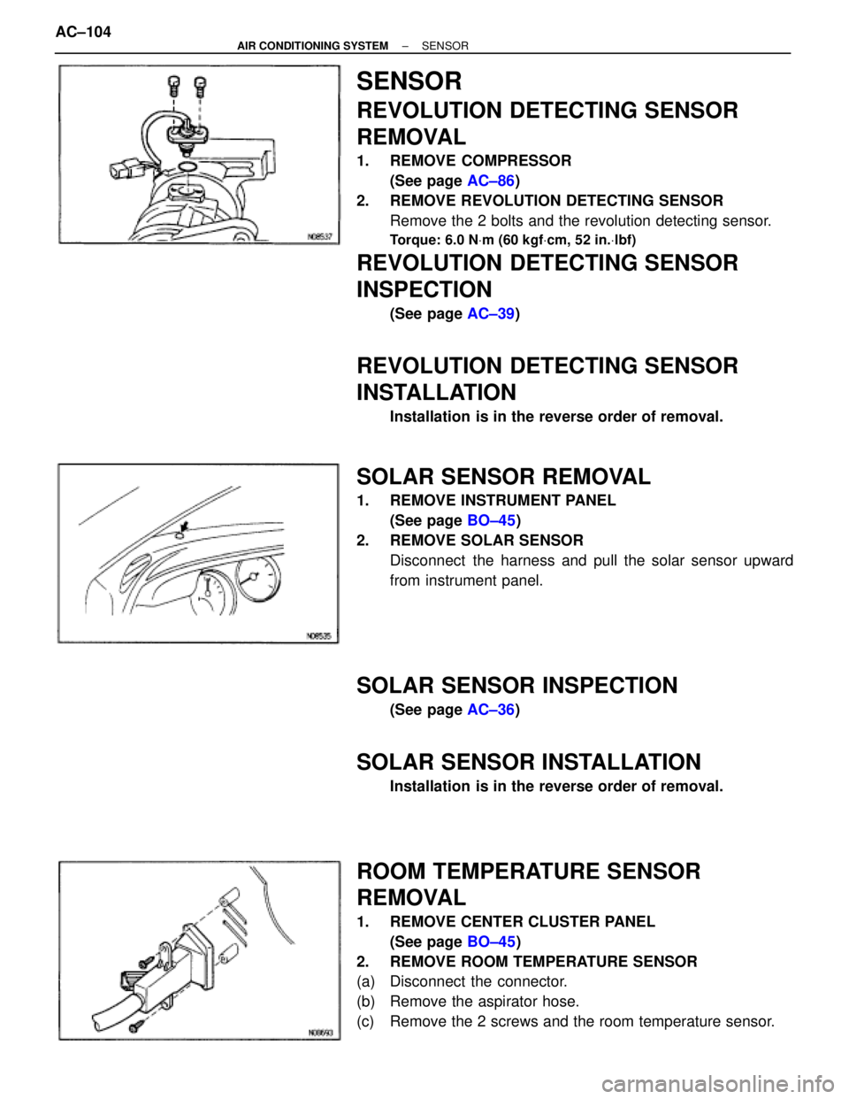
REVOLUTION DETECTING SENSOR
REMOVAL
1. REMOVE COMPRESSOR
(See page AC±86)
2. REMOVE REVOLUTION DETECTING SENSOR
Remove the 2 bolts and the revolution detecting sensor.
Torque: 6.0 NVm (60 kgfVcm, 52 in.Vlbf)
REVOLUTION DETECTING SENSOR
INSPECTION
(See page AC±39)
REVOLUTION DETECTING SENSOR
INSTALLATION
Installation is in the reverse order of removal.
SOLAR SENSOR REMOVAL
1. REMOVE INSTRUMENT PANEL
(See page BO±45)
2. REMOVE SOLAR SENSOR
Disconnect the harness and pull the solar sensor upward
from instrument panel.
SOLAR SENSOR INSPECTION
(See page AC±36)
SOLAR SENSOR INSTALLATION
Installation is in the reverse order of removal.
ROOM TEMPERATURE SENSOR
REMOVAL
1. REMOVE CENTER CLUSTER PANEL
(See page BO±45)
2. REMOVE ROOM TEMPERATURE SENSOR
(a) Disconnect the connector.
(b) Remove the aspirator hose.
(c) Remove the 2 screws and the room temperature sensor. AC±104
± AIR CONDITIONING SYSTEMSENSOR
Page 731 of 2543
INSPECTION PROCEDURE
(See page BE±123).
Check harness and connector between theft deterrent and door lock ECU
and indicator light, indicator light and body ground (See page IN±30).
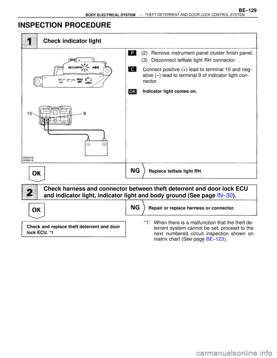
(2) Remove instrument panel cluster finish panel.
(3) Disconnect telltale light RH connector.
Connect positive (+) lead to terminal 10 and neg-
ative (±) lead to terminal 9 of indicator light con-
nector.
Indicator light comes on.
Replace telltale light RH.
Repair or replace harness or connector.
Check and replace theft deterrent and door
lock ECU. *1*1: When there is a malfunction that the theft de-
terrent system cannot be set, proceed to the
next numbered circuit inspection shown on
matrix chart (See page BE±123).
Check indicator light
± BODY ELECTRICAL SYSTEMBE±129THEFT DETERRENT AND DOOR LOCK CONTROL SYSTEM
Page 853 of 2543
INSTRUMENT PANEL REMOVAL
1. REMOVE STEERING WHEEL
(See page SR±14)
CAUTION:
wWhen storing the wheel pad, keep the upper surface of
the pad facing upward.
wNever disassemble the steering wheel pad.
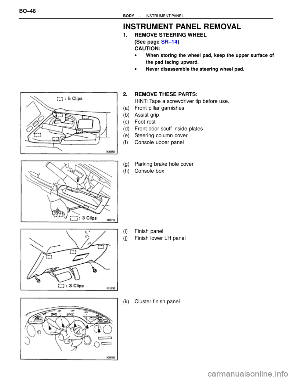
2. REMOVE THESE PARTS:
HINT: Tape a screwdriver tip before use.
(a) Front pillar garnishes
(b) Assist grip
(c) Foot rest
(d) Front door scuff inside plates
(e) Steering column cover
(f) Console upper panel
(g) Parking brake hole cover
(h) Console box
(i) Finish panel
(j) Finish lower LH panel
(k) Cluster finish panel BO±48
± BODYINSTRUMENT PANEL
Page 854 of 2543
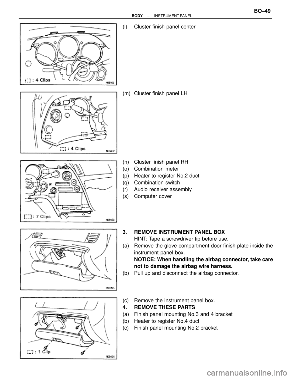
(l) Cluster finish panel center
(m) Cluster finish panel LH
(n) Cluster finish panel RH
(o) Combination meter
(p) Heater to register No.2 duct
(q) Combination switch
(r) Audio receiver assembly
(s) Computer cover
3. REMOVE INSTRUMENT PANEL BOX
HINT: Tape a screwdriver tip before use.
(a) Remove the glove compartment door finish plate inside the
instrument panel box.
NOTICE: When handling the airbag connector, take care
not to damage the airbag wire harness.
(b) Pull up and disconnect the airbag connector.
(c) Remove the instrument panel box.
4. REMOVE THESE PARTS
(a) Finish panel mounting No.3 and 4 bracket
(b) Heater to register No.4 duct
(c) Finish panel mounting No.2 bracket
± BODYINSTRUMENT PANELBO±49