Page 119 of 2543

INTRODUCTIONGLOSSARY OF SAE AND TOYOTA TERMS -
IN-8
IACIdle Air ControlIdle Speed Control (ISC)
IATIntake Air TemperatureIntake or Inlet Air Temperature
ICMIgnition Control Module-
IFIIndirect Fuel InjectionIndirect Injection
IFSInertia Fuel-Shutoff-
ISCIdle Speed Control-
KSKnock SensorKnock Sensor
MAFMass Air FlowAir Flow Meter
MAPManifold Absolute PressureManifold Pressure
Intake Vacuum
MCMixture Control
Electric Bleed Air Control Valve (EBCV)
Mixture Control Valve (MCV)
Electric Air Control Valve (EACV)
MDPManifold Differential Pressure-
MFIMultiport Fuel InjectionElectronic Fuel Injection (EFI)
MILMalfunction Indicator LampCheck Engine Light
MSTManifold Surface Temperature-
MVZManifold Vacuum Zone-
NVRAMNon-V olatile Random Access Memory-
O2SOxygen SensorOxygen Sensor, O2 Sensor (O2S)
OBDOn-Board DiagnosticOn-Board Diagnostic (OBD)
OCOxidation Catalytic ConverterOxidation Catalyst Converter (OC), CCo
OPOpen LoopOpen Loop
PAIRPulsed Secondary Air InjectionAir Suction (AS)
PCMPowertrain Control Module-
PNPPark/Neutral Position-
PROMProgrammable Read Only Memory-
PSPPower Steering Pressure-
PTOXPeriodic Trap OxidizerDiesel Particulate Filter (DPF)
Diesel Particulate Trap (DPT)
RAMRandom Access MemoryRandom Access Memory (RAM)
RMRelay Module-
ROMRead Only MemoryRead Only Memory (ROM)
RPMEngine SpeedEngine Speed
SCSuperchargerSupercharger
SCBSupercharger Bypass-
SFISequential Multiport Fuel InjectionElectronic Fuel Injection (EFI), Sequential Injection
SPLSmoke Puff Limiter-
SRIService Reminder Indicator-
SRTSystem Readiness Test-
STScan Tool-
TBThrottle BodyThrottle Body
TBIThrottle Body Fuel InjectionSingle Point Injection
Central Fuel Injection (Ci)
TCTurbochargerTurbocharger
TCCTorque Converter ClutchTorque Converter
TCMTransmission Control ModuleTransmission ECU (Electronic Control Unit)
TPThrottle PositionThrottle Position
TRTransmission Range-
Page 1114 of 2543
EVAPORATIVE EMISSION (EVAP)
CONTROL SYSTEM
FUEL VAPOR LINES, FUEL TANK AND
TANK CAP INSPECTION
1. VISUALLY INSPECT LINES AND CONNECTIONS
Look for loose connections, sharp bends or damage.
2. VISUALLY INSPECT FUEL TANK
Look for deformation, cracks or fuel leakage.
3. VISUALLY INSPECT FUEL TANK CAP
Check if the cap and/or gasket are deformed or damaged.
If necessary, repair or replace the cap.
CHARCOAL CANISTER INSPECTION
1. REMOVE CHARCOAL CANISTER
2. VISUALLY INSPECT CHARCOAL CANISTER
Look for cracks or damage.
3. CHECK FOR CLOGGED FILTER AND STUCK CHECK
VA LV E
(a) Using low pressure compressed air (4.71 kPa (0.048
kgf/cm
2, 0.68 psi)), blow into port B and check that air flows
without resistance from the other ports. EG±166
± ENGINEEMISSION CONTROL SYSTEMS (2JZ±GE)
Page 1115 of 2543
(b) Blow air (4.71 kPa (0.048 kgf/cm2, 0.68 psi)) into port A, and
check that air does not flow from the other ports.
If operation is not as specified, replace the charcoal canister.
4. CLEAN FILTER IN CANISTER
Clean the filter by blowing 294 kPa (3 kgf/cm
2, 43 psi) of com-
pressed air into port B while holding port A closed.
NOTICE:
�Do not attempt to wash the canister.
�No activated carbon should come out.
5. REINSTALL CHARCOAL CANISTER
VSV INSPECTION
(See VSV for EVAP in SFI System)
CHECK VALVE INSPECTION
1. REMOVE CHECK VALVE
2. INSPECT CHECK VALVE
(a) Check that air flows from the blue port to the black port.
(b) Check that air does not flow from the black port to the blue
port.
If operation is not as specified, replace the check valve.
3. REINSTALL CHECK VALVE
HINT: Install the check valve with the black port facing the
port P side of the throttle body.
± ENGINEEMISSION CONTROL SYSTEMS (2JZ±GE)EG±167
Page 1116 of 2543

EXHAUST GAS RECIRCULATION (EGR)
SYSTEM
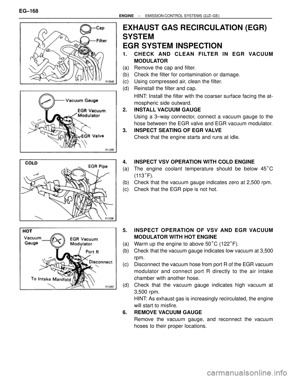
EGR SYSTEM INSPECTION
1. CHECK AND CLEAN FILTER IN EGR VACUUM
MODULATOR
(a) Remove the cap and filter.
(b) Check the filter for contamination or damage.
(c) Using compressed air, clean the filter.
(d) Reinstall the filter and cap.
HINT: Install the filter with the coarser surface facing the at-
mospheric side outward.
2. INSTALL VACUUM GAUGE
Using a 3±way connector, connect a vacuum gauge to the
hose between the EGR valve and EGR vacuum modulator.
3. INSPECT SEATING OF EGR VALVE
Check that the engine starts and runs at idle.
4. INSPECT VSV OPERATION WITH COLD ENGINE
(a) The engine coolant temperature should be below 45°C
(113°F).
(b) Check that the vacuum gauge indicates zero at 2,500 rpm.
(c) Check that the EGR pipe is not hot.
5. INSPECT OPERATION OF VSV AND EGR VACUUM
MODULATOR WITH HOT ENGINE
(a) Warm up the engine to above 50°C (122°F).
(b) Check that the vacuum gauge indicates low vacuum at 3,500
rpm.
(c) Disconnect the vacuum hose from port R of the EGR vacuum
modulator and connect port R directly to the air intake
chamber with another hose.
(d) Check that the vacuum gauge indicates high vacuum at
3,500 rpm.
HINT: As exhaust gas is increasingly recirculated, the engine
will start to misfire.
6. REMOVE VACUUM GAUGE
Remove the vacuum gauge, and reconnect the vacuum
hoses to their proper locations. EG±168
± ENGINEEMISSION CONTROL SYSTEMS (2JZ±GE)
Page 1117 of 2543

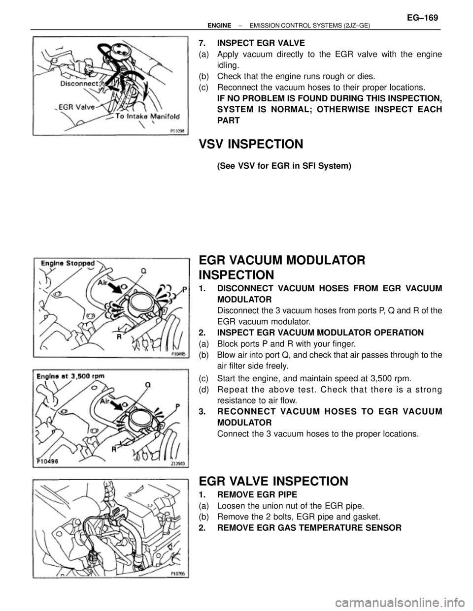
7. INSPECT EGR VALVE
(a) Apply vacuum directly to the EGR valve with the engine
idling.
(b) Check that the engine runs rough or dies.
(c) Reconnect the vacuum hoses to their proper locations.
IF NO PROBLEM IS FOUND DURING THIS INSPECTION,
SYSTEM IS NORMAL; OTHERWISE INSPECT EACH
PART
VSV INSPECTION
(See VSV for EGR in SFI System)
EGR VACUUM MODULATOR
INSPECTION
1. DISCONNECT VACUUM HOSES FROM EGR VACUUM
MODULATOR
Disconnect the 3 vacuum hoses from ports P, Q and R of the
EGR vacuum modulator.
2. INSPECT EGR VACUUM MODULATOR OPERATION
(a) Block ports P and R with your finger.
(b) Blow air into port Q, and check that air passes through to the
air filter side freely.
(c) Start the engine, and maintain speed at 3,500 rpm.
(d) Repeat the above test. Check that there is a strong
resistance to air flow.
3. RECONNECT VACUUM HOSES TO EGR VACUUM
MODULATOR
Connect the 3 vacuum hoses to the proper locations.
EGR VALVE INSPECTION
1. REMOVE EGR PIPE
(a) Loosen the union nut of the EGR pipe.
(b) Remove the 2 bolts, EGR pipe and gasket.
2. REMOVE EGR GAS TEMPERATURE SENSOR
± ENGINEEMISSION CONTROL SYSTEMS (2JZ±GE)EG±169
Page 1127 of 2543
EVAPORATIVE EMISSION (EVAP)
CONTROL SYSTEM
FUEL VAPOR LINES, FUEL TANK AND
TANK CAP INSPECTION
1. VISUALLY INSPECT LINES AND CONNECTIONS
Look for loose connections, sharp bends or damage.
2. VISUALLY INSPECT FUEL TANK
Look for deformation, cracks or fuel leakage.
3. VISUALLY INSPECT FUEL TANK CAP
Check if the cap and/or gasket are deformed or damaged.
If necessary, repair or replace the cap.
CHARCOAL CANISTER INSPECTION
1. REMOVE CHARCOAL CANISTER
2. VISUALLY INSPECT CHARCOAL CANISTER
Look for cracks or damage.
3. CHECK FOR CLOGGED FILTER AND STUCK CHECK
VA LV E
(a) Using low pressure compressed air (4.71 kPa (0.048
kgf/cm
2, 0.68 psi)), blow into port C and check that air flows
without resistance from the other ports. EG±178
± ENGINEEMISSION CONTROL SYSTEMS (2JZ±GTE)
Page 1128 of 2543

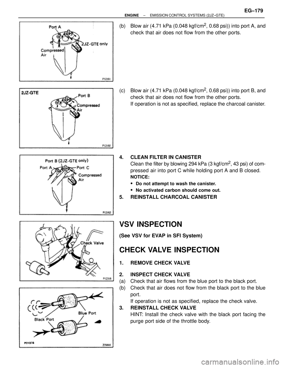
(b) Blow air (4.71 kPa (0.048 kgf/cm2, 0.68 psi)) into port A, and
check that air does not flow from the other ports.
(c) Blow air (4.71 kPa (0.048 kgf/cm
2, 0.68 psi)) into port B, and
check that air does not flow from the other ports.
If operation is not as specified, replace the charcoal canister.
4. CLEAN FILTER IN CANISTER
Clean the filter by blowing 294 kPa (3 kgf/cm
2, 43 psi) of com-
pressed air into port C while holding port A and B closed.
NOTICE:
� Do not attempt to wash the canister.
� No activated carbon should come out.
5. REINSTALL CHARCOAL CANISTER
VSV INSPECTION
(See VSV for EVAP in SFI System)
CHECK VALVE INSPECTION
1. REMOVE CHECK VALVE
2. INSPECT CHECK VALVE
(a) Check that air flows from the blue port to the black port.
(b) Check that air does not flow from the black port to the blue
port.
If operation is not as specified, replace the check valve.
3. REINSTALL CHECK VALVE
HINT: Install the check valve with the black port facing the
purge port side of the throttle body.
± ENGINEEMISSION CONTROL SYSTEMS (2JZ±GTE)EG±179
Page 1129 of 2543

EXHAUST GAS RECIRCULATION (EGR)
SYSTEM
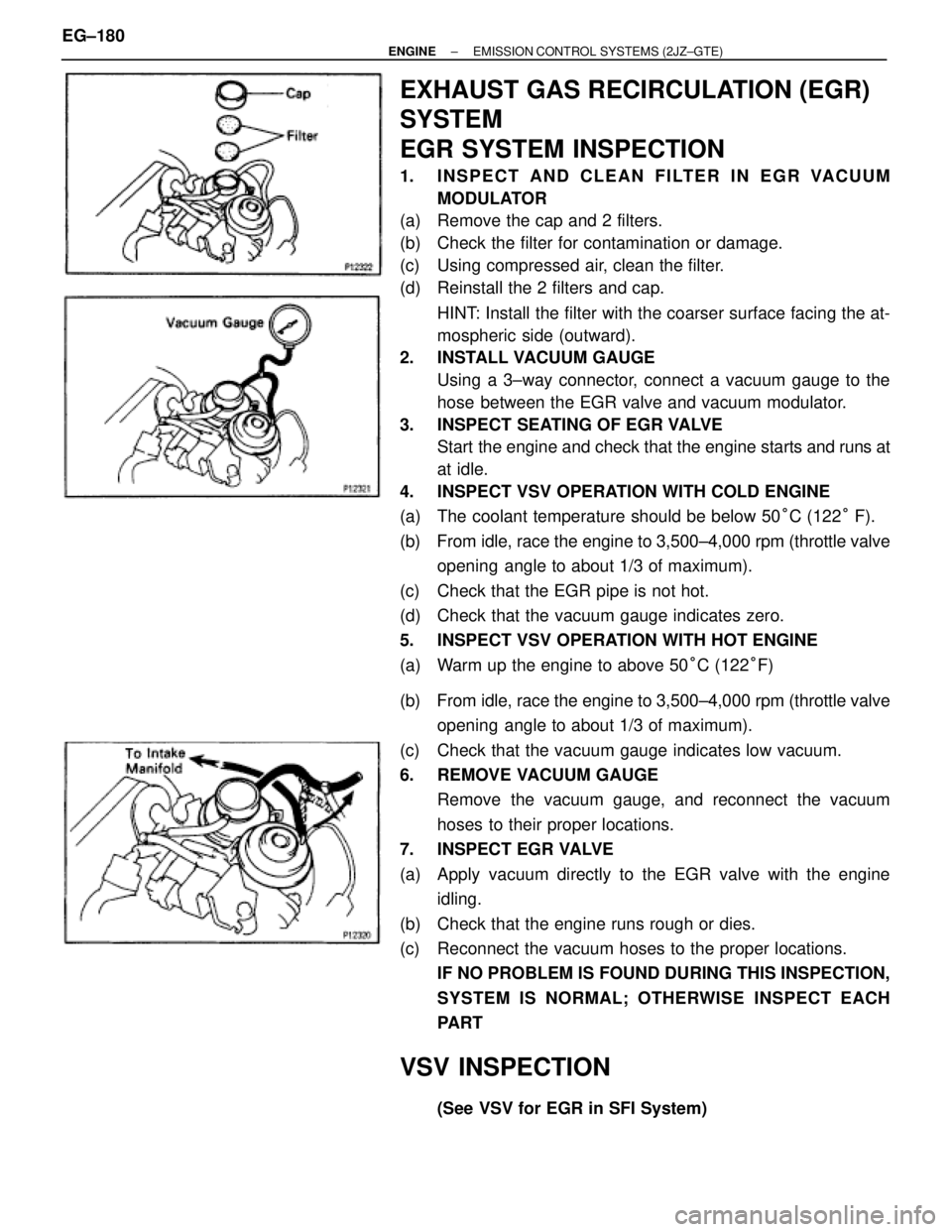
EGR SYSTEM INSPECTION
1. INSPECT AND CLEAN FILTER IN EGR VACUUM
MODULATOR
(a) Remove the cap and 2 filters.
(b) Check the filter for contamination or damage.
(c) Using compressed air, clean the filter.
(d) Reinstall the 2 filters and cap.
HINT: Install the filter with the coarser surface facing the at-
mospheric side (outward).
2. INSTALL VACUUM GAUGE
Using a 3±way connector, connect a vacuum gauge to the
hose between the EGR valve and vacuum modulator.
3. INSPECT SEATING OF EGR VALVE
Start the engine and check that the engine starts and runs at
at idle.
4. INSPECT VSV OPERATION WITH COLD ENGINE
(a) The coolant temperature should be below 50°C (122° F).
(b) From idle, race the engine to 3,500±4,000 rpm (throttle valve
opening angle to about 1/3 of maximum).
(c) Check that the EGR pipe is not hot.
(d) Check that the vacuum gauge indicates zero.
5. INSPECT VSV OPERATION WITH HOT ENGINE
(a) Warm up the engine to above 50°C (122°F)
(b) From idle, race the engine to 3,500±4,000 rpm (throttle valve
opening angle to about 1/3 of maximum).
(c) Check that the vacuum gauge indicates low vacuum.
6. REMOVE VACUUM GAUGE
Remove the vacuum gauge, and reconnect the vacuum
hoses to their proper locations.
7. INSPECT EGR VALVE
(a) Apply vacuum directly to the EGR valve with the engine
idling.
(b) Check that the engine runs rough or dies.
(c) Reconnect the vacuum hoses to the proper locations.
IF NO PROBLEM IS FOUND DURING THIS INSPECTION,
SYSTEM IS NORMAL; OTHERWISE INSPECT EACH
PART
VSV INSPECTION
(See VSV for EGR in SFI System) EG±180
± ENGINEEMISSION CONTROL SYSTEMS (2JZ±GTE)