Page 3 of 2543

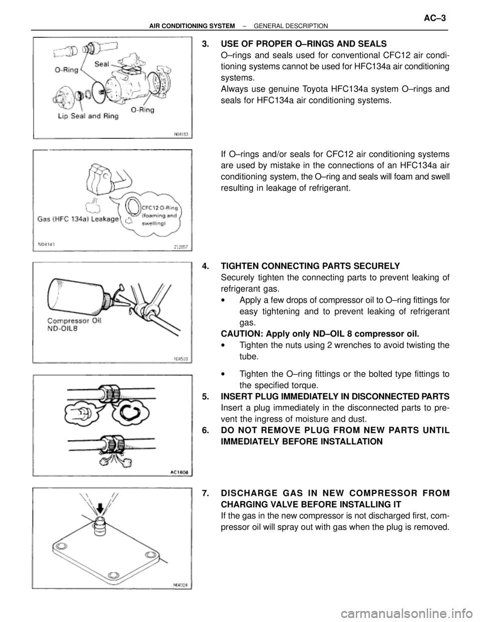
3. USE OF PROPER O±RINGS AND SEALS
O±rings and seals used for conventional CFC12 air condi-
tioning systems cannot be used for HFC134a air conditioning
systems.
Always use genuine Toyota HFC134a system O±rings and
seals for HFC134a air conditioning systems.
If O±rings and/or seals for CFC12 air conditioning systems
are used by mistake in the connections of an HFC134a air
conditioning system, the O±ring and seals will foam and swell
resulting in leakage of refrigerant.
4. TIGHTEN CONNECTING PARTS SECURELY
Securely tighten the connecting parts to prevent leaking of
refrigerant gas.
wApply a few drops of compressor oil to O±ring fittings for
easy tightening and to prevent leaking of refrigerant
gas.
CAUTION: Apply only ND±OIL 8 compressor oil.
wTighten the nuts using 2 wrenches to avoid twisting the
tube.
wTighten the O±ring fittings or the bolted type fittings to
the specified torque.
5. INSERT PLUG IMMEDIATELY IN DISCONNECTED PARTS
Insert a plug immediately in the disconnected parts to pre-
vent the ingress of moisture and dust.
6. DO NOT REMOVE PLUG FROM NEW PARTS UNTIL
IMMEDIATELY BEFORE INSTALLATION
7. DISCHARGE GAS IN NEW COMPRESSOR FROM
CHARGING VALVE BEFORE INSTALLING IT
If the gas in the new compressor is not discharged first, com-
pressor oil will spray out with gas when the plug is removed.
± AIR CONDITIONING SYSTEMGENERAL DESCRIPTIONAC±3
Page 78 of 2543
REFRIGERANT LINES
TIGHTENING TORQUE OF REFRIGERATION LINES
ON±VEHICLE INSPECTION
1. INSPECT HOSES AND TUBES FOR LEAKAGE
Using a gas leak tester, check for leakage of refrigerant.
2. INSPECT HOSE AND TUBE CONNECTIONS FOR
LOOSENESS AC±78
± AIR CONDITIONING SYSTEMREFRIGERANT LINES
Page 79 of 2543

REFRIGERANT LINES REPLACEMENT
1. DISCHARGE REFRIGERANT IN REFRIGERATION
SYSTEM
2. REPLACE FAULTY TUBE OR HOSE
NOTICE: To prevent the intrusion of moisture or dirt,
caps should be placed on hose or tube ends immediate-
ly.
3. TORQUE CONNECTIONS TO SPECIFIED TORQUE
NOTICE: Connections should not be torqued tighter than
the specified torque.
Compressor X Suction tube
Torque: 10 NVm (100 kgfVcm, 7 ftVlbf)
Compressor X Discharge tube
Torque: 10 NVm (100 kgfVcm, 7 ftVlbf)
Condenser X Discharge tube
Torque: 10 NVm (100 kgfVcm, 7 ftVlbf)
Condenser X Liquid tube
Torque: 10 NVm (100 kgfVcm, 7 ftVlbf)
Receiver X Liquid tube
Torque: 5.4 NVm (55 kgfVcm, 48 in.Vlbf)
A/C unit X Liquid tube
Torque: 10 NVm (100 kgfVcm, 7 ftVlbf)
A/C unit X Suction tube
Torque: 10 NVm (100 kgfVcm, 7 ftVlbf)
Evaporator X Expansion valve
Torque: 5.4 NVm (55 kgfVcm, 48 in.Vlbf)
Discharge lines
Torque: 10 NVm (100 kgfVcm, 7 ftVlbf)
Liquid lines
Torque: 10 NVm (100 kgfVcm, 7 ftVlbf)
Suction lines
Torque: 10 NVm (100 kgfVcm, 7 ftVlbf)
4. EVACUATE AIR IN REFRIGERATION SYSTEM AND
CHARGE WITH REFRIGERANT
Specified amount:
700 + 50 g (24.96 + 1.76 oz.)
5. INSPECT FOR LEAKAGE OF REFRIGERANT
Using a gas leak tester, check for leakage of refrigerant.
6. INSPECT AIR CONDITIONING OPERATION
± AIR CONDITIONING SYSTEMREFRIGERANT LINESAC±79
Page 80 of 2543

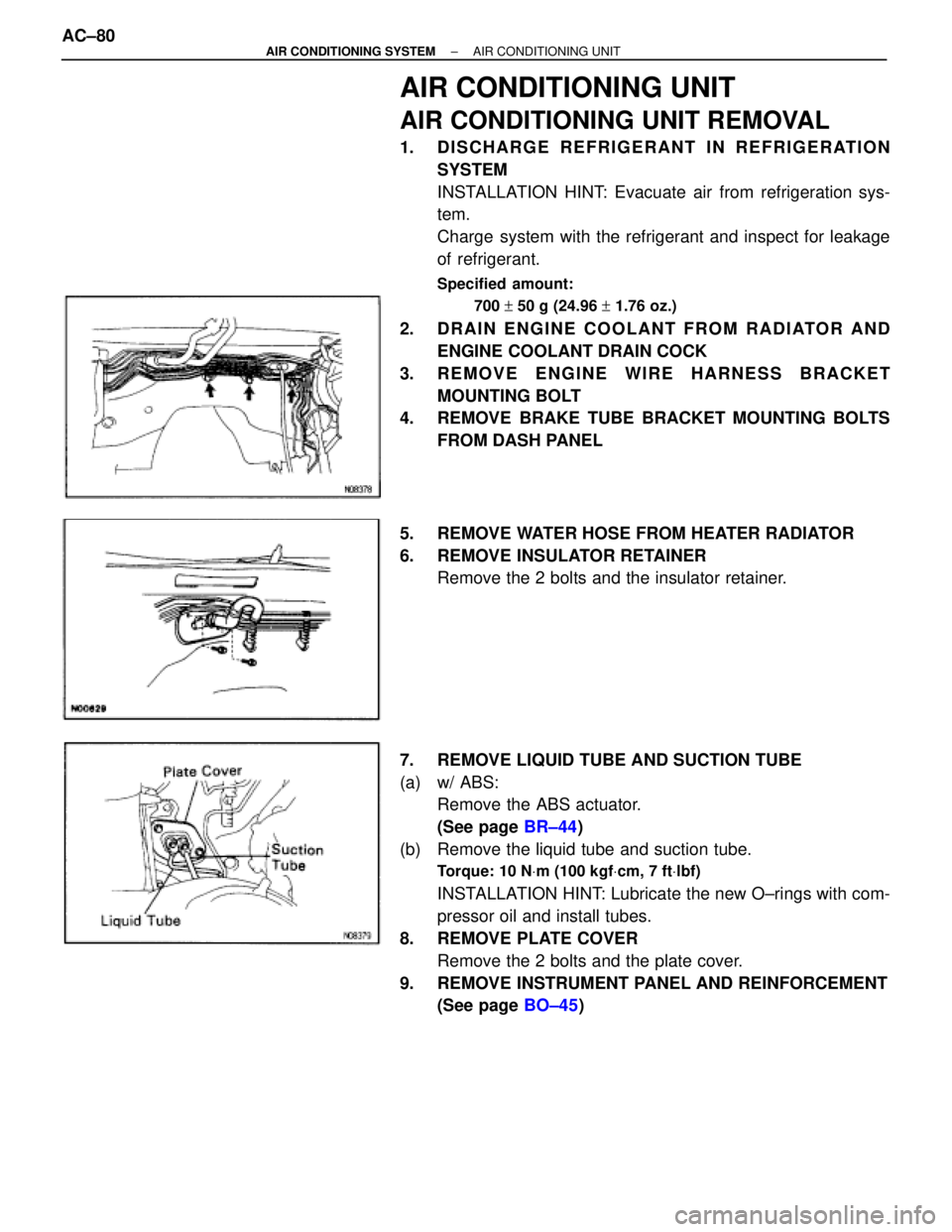
AIR CONDITIONING UNIT
AIR CONDITIONING UNIT REMOVAL
1. DISCHARGE REFRIGERANT IN REFRIGERATION
SYSTEM
INSTALLATION HINT: Evacuate air from refrigeration sys-
tem.
Charge system with the refrigerant and inspect for leakage
of refrigerant.
Specified amount:
700 + 50 g (24.96 + 1.76 oz.)
2. DRAIN ENGINE COOLANT FROM RADIATOR AND
ENGINE COOLANT DRAIN COCK
3. REMOVE ENGINE WIRE HARNESS BRACKET
MOUNTING BOLT
4. REMOVE BRAKE TUBE BRACKET MOUNTING BOLTS
FROM DASH PANEL
5. REMOVE WATER HOSE FROM HEATER RADIATOR
6. REMOVE INSULATOR RETAINER
Remove the 2 bolts and the insulator retainer.
7. REMOVE LIQUID TUBE AND SUCTION TUBE
(a) w/ ABS:
Remove the ABS actuator.
(See page BR±44)
(b) Remove the liquid tube and suction tube.
Torque: 10 NVm (100 kgfVcm, 7 ftVlbf)
INSTALLATION HINT: Lubricate the new O±rings with com-
pressor oil and install tubes.
8. REMOVE PLATE COVER
Remove the 2 bolts and the plate cover.
9. REMOVE INSTRUMENT PANEL AND REINFORCEMENT
(See page BO±45) AC±80
± AIR CONDITIONING SYSTEMAIR CONDITIONING UNIT
Page 83 of 2543

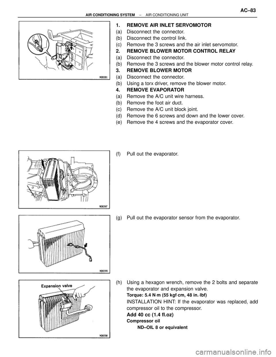
1. REMOVE AIR INLET SERVOMOTOR
(a) Disconnect the connector.
(b) Disconnect the control link.
(c) Remove the 3 screws and the air inlet servomotor.
2. REMOVE BLOWER MOTOR CONTROL RELAY
(a) Disconnect the connector.
(b) Remove the 3 screws and the blower motor control relay.
3. REMOVE BLOWER MOTOR
(a) Disconnect the connector.
(b) Using a torx driver, remove the blower motor.
4. REMOVE EVAPORATOR
(a) Remove the A/C unit wire harness.
(b) Remove the foot air duct.
(c) Remove the A/C unit block joint.
(d) Remove the 6 screws and down and the lower cover.
(e) Remove the 4 screws and the evaporator cover.
(f) Pull out the evaporator.
(g) Pull out the evaporator sensor from the evaporator.
(h) Using a hexagon wrench, remove the 2 bolts and separate
the evaporator and expansion valve.
Torque: 5.4 NVm (55 kgfVcm, 48 in.Vlbf)
INSTALLATION HINT: If the evaporator was replaced, add
compressor oil to the compressor.
Add 40 cc (1.4 fl.oz)
Compressor oil
ND±OIL 8 or equivalent
± AIR CONDITIONING SYSTEMAIR CONDITIONING UNITAC±83
Page 87 of 2543
MAGNETIC CLUTCH DISASSEMBLY
1. REMOVE PRESSURE PLATE
(a) Using SST and socket wrench, remove the shaft bolt.
SST 07112±76060
Torque: 14 NVm (140 kgfVcm, 10ftVlbf)
(b) Install SST on the pressure plate.
SST 07112±66040
± AIR CONDITIONING SYSTEMCOMPRESSORAC±87
Page 90 of 2543

(c) Check the clearance between the pressure plate and rotor,
then connect the negative (±) terminal of the battery.
Standard clearance:
0.5 + 0.15 mm (0.020 + 0.0059 in.)
If the clearance is not within specification, adjust the clear-
ance using shims to obtain the standard clearance.
Shim Thickness:
0.1 mm (0.004 in.)
0.3 mm (0.012 in.)
0.5 mm (0.020 in.)
COMPRESSOR INSTALLATION
1. INSTALL COMPRESSOR
(a) Install the stud bolt.
Torque: 26 NVm (265 kgfVcm, 19 ftVlbf)
(b) Install the compressor with 4 bolts and nut.
Torque: 52 NVm (530 kgfVcm, 38 ftVlbf)
(c) Connect the magnetic clutch connector.
(d) Install the engine under cover.
2. CONNECT DISCHARGE HOSE AND SUCTION HOSE TO
COMPRESSOR
NOTICE: Hoses should be connected immediately after
the caps have been removed.
Torque: 10 NVm (100 kgfVcm, 7 ftVlbf)
3. INSTALL POWER STEERING PUMP
Install the power steering pump with 2 bolts.
Torque: 58 NVm (590 kgfVcm, 43 ftVlbf)
4. INSTALL DRIVE BELT
5. INSTALL BATTERY
6. EVACUATE AIR IN REFRIGERATION SYSTEM AND
CHARGE WITREFRIGERANT
Specified amount:
700 + 50 g (24.96 + 1.76 oz.)
7. INSPECT FOR LEAKAGE OF REFRIGERANT
Using a gas leak tester, check for leakage of refrigerant.
If there is leakage, check the tightening torque at the joints.
8. INSPECT A/C OPERATION AC±90
± AIR CONDITIONING SYSTEMCOMPRESSOR
Page 91 of 2543

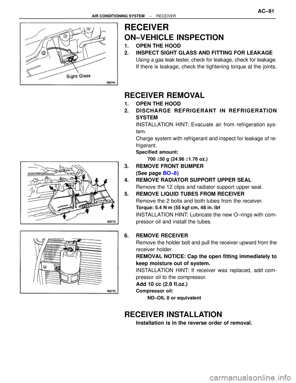
RECEIVER
ON±VEHICLE INSPECTION
1. OPEN THE HOOD
2. INSPECT SIGHT GLASS AND FITTING FOR LEAKAGE
Using a gas leak tester, check for leakage, check for leakage.
If there is leakage, check the tightening torque at the joints.
RECEIVER REMOVAL
1. OPEN THE HOOD
2. DISCHARGE REFRIGERANT IN REFRIGERATION
SYSTEM
INSTALLATION HINT: Evacuate air from refrigeration sys-
tem.
Charge system with refrigerant and inspect for leakage of re-
frigerant.
Specified amount:
700 +50 g (24.96 +1.76 oz.)
3. REMOVE FRONT BUMPER
(See page BO±8)
4. REMOVE RADIATOR SUPPORT UPPER SEAL
Remove the 12 clips and radiator support upper seal.
5. REMOVE LIQUID TUBES FROM RECEIVER
Remove the 2 bolts and both tubes from the receiver.
Torque: 5.4 NVm (55 kgfVcm, 48 in.Vlbf
INSTALLATION HINT: Lubricate the new O±rings with com-
pressor oil and install the tubes.
6. REMOVE RECEIVER
Remove the holder bolt and pull the receiver upward from the
receiver holder.
REMOVAL NOTICE: Cap the open fitting immediately to
keep moisture out of system.
INSTALLATION HINT: If receiver was replaced, add com-
pressor oil to the compressor.
Add 10 cc (2.9 fl.oz.)
Compressor oil:
ND±OIL 8 or equivalent
RECEIVER INSTALLATION
Installation is in the reverse order of removal.
± AIR CONDITIONING SYSTEMRECEIVERAC±91