Page 9 of 2543
PREPARATION
SST (SPECIAL SERVICE TOOLS)
Air Conditioner Service Tool Set
Refrigerant Drain Service Valve
T±Joint
Quick Coupler
Quick Coupler
Refrigerant Charging Gauge
Refrigerant Charging Hose
Refrigerant Charging Hose
Refrigerant Charging Hose
Magnetic Clutch Remover
Magnetic Clutch Stopper
Snap Ring Pliers
Gas Leak Detector Assembly
Discharge (diam. 16 mm)
Suction (diam. 16 mm)
Suction (Blue)
Discharge (Red)
Utility (Green)
± AIR CONDITIONING SYSTEMPREPARATIONAC±9
Page 22 of 2543
Step No.
Conditions
Blower
MotorAir Flow
ventAir Inlet
damper
Set
Temperature
°C (°F)
Magnetic
clutchAir mix
damper
ACTUATOR CHECK
1. After entering the sensor check mode, press the R/F switch.
2. Turn the temperature set dial and change it to step operation.
Each time the dial is turned, the actuator operation changes
by 1 step.
HINT:
wCheck the change of actuator operation visually and by
hand.
wTo cancel the check mode, press the OFF switch. AC±22
± AIR CONDITIONING SYSTEMTROUBLESHOOTING
Page 40 of 2543
Blinking Light FRS Pressure Switch Circuit
CIRCUIT DESCRIPTION
The pressure switch sends the appropriate signals to the A/C amplifier when the air conditioning refrig-
erant pressure drops too low or rises too high. When the A/C amplifier receives these signals, it outputs
signals via the ECM to switch OFF the compressor relay and turns the magnetic clutch OFF.
Diagnostic Sensor Check Detecting ConditionTrouble Area
�Pressure switch
�Harness or connector between pressure switch
and A/C amplifier
�Refrigerant pipe line
�A/C amplifierOpen in pressure sensor circuit
Abnormal refrigerant pressure
below 196 kPa (2.0 kgf/cm2, 28 psi)
over 3,140 kPa (32.0 kgf/cm2, 455 psi)
AC±40± AIR CONDITIONING SYSTEMTROUBLESHOOTING
Page 62 of 2543
Compressor Circuit
CIRCUIT DESCRIPTION
The A/C amplifier outputs the magnetic clutch ON signal from terminal MGC to the ECM. When the ECM re-
ceives this signal, it sends a signal from terminal ACMG and switches the air conditioning magnetic clutch relay
ON, thus turning the air conditioning compressor magnetic clutch ON.
AC±62± AIR CONDITIONING SYSTEMTROUBLESHOOTING
Page 63 of 2543
Check voltage between terminal A/C IN of A/C amplifier connector and
body ground.
Check air conditioning compressor magnetic clutch.
Go to step
Check for open and short in harness and connector between air
conditioner compressor and magnetic clutch relay (See page IN±30).
Repair or replace harness or connector.
Go to step
1. Remove A/C amplifier with connectors still con
nected.
2. Start the engine.
Check voltage between terminal A/C IN of A/C amplifi-
er connector and body ground when magnetic clutch is
on and off by A/C switch.
Magnetic ClutchVoltage
ON
OFF Below 1 V
Connect positive (+) lead connected to battery to
magnetic clutch connector terminal 4.
Disconnect magnetic clutch connector.
Magnetic clutch is energized.
Repair air conditioning compressor magnetic
clutch.
10 ± 14 V
INSPECTION PROCEDURE
± AIR CONDITIONING SYSTEMTROUBLESHOOTINGAC±63
Page 64 of 2543
Go to step
Check and replace ECM.
Check voltage between terminal A/C of ECM and body ground.
Check voltage between terminal MGC of A/C amplifier connector and
body ground.
Magnetic ClutchVoltage
ON
OFF
Below 1 V
4 ± 6 V
1. Remove A/C amplifier with connectors still con
nected.
2. Start the engine.
Check voltage between terminal A/C IN of A/C amplifi-
er connector and body ground when magnetic clutch is
on and off by A/C switch.
1. Remove the ECM with connectors still con
nected.
2. Turn ignition switch on.
Magnetic ClutchVoltage
ON
OFF
Below 1 V
10 ± 14 V
Check and replace A/C amplifier.
Repair or replace harness or connector.
Check for open and short in harness and connector between A/C am-
plifier and ECM (See page IN±30).
1. Push the A/C switch on.
2. Measure voltage between terminal A/C of the
ECM connector and body ground.
AC±64± AIR CONDITIONING SYSTEMTROUBLESHOOTING
Page 65 of 2543

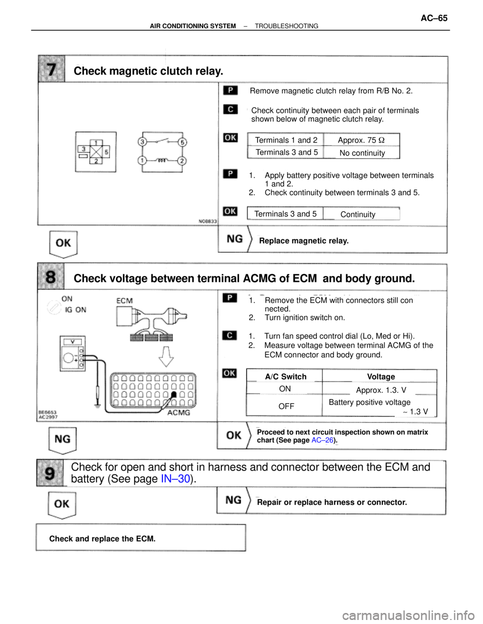
Remove magnetic clutch relay from R/B No. 2.
Check continuity between each pair of terminals
shown below of magnetic clutch relay.
Terminals 1 and 2
Terminals 3 and 5
Terminals 3 and 5
No continuity
Continuity
Replace magnetic relay.
Check and replace the ECM.
Repair or replace harness or connector.
A/C SwitchVoltage
ON
OFF
Check for open and short in harness and connector between the ECM and
battery (See page IN±30).
Approx. 1.3. V
Approx. 75 �
Battery positive voltage
Check magnetic clutch relay.
Check voltage between terminal ACMG of ECM and body ground.
1. Apply battery positive voltage between terminals
1 and 2.
2. Check continuity between terminals 3 and 5.
1. Remove the ECM with connectors still con
nected.
2. Turn ignition switch on.
1. Turn fan speed control dial (Lo, Med or Hi).
2. Measure voltage between terminal ACMG of the
ECM connector and body ground.
Proceed to next circuit inspection shown on matrix
chart (See page AC±26).
~ 1.3 V
± AIR CONDITIONING SYSTEMTROUBLESHOOTINGAC±65
Page 77 of 2543

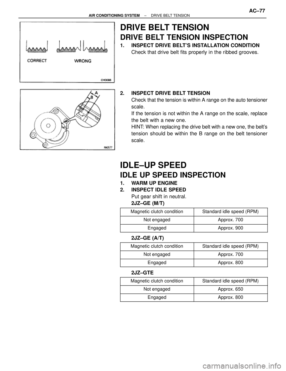
DRIVE BELT TENSION
DRIVE BELT TENSION INSPECTION
1. INSPECT DRIVE BELT'S INSTALLATION CONDITION
Check that drive belt fits properly in the ribbed grooves.
2. INSPECT DRIVE BELT TENSION
Check that the tension is within A range on the auto tensioner
scale.
If the tension is not within the A range on the scale, replace
the belt with a new one.
HINT: When replacing the drive belt with a new one, the belt's
tension should be within the B range on the belt tensioner
scale.
IDLE±UP SPEED
IDLE UP SPEED INSPECTION
1. WARM UP ENGINE
2. INSPECT IDLE SPEED
Put gear shift in neutral.
2JZ±GE (M/T)
����������� �
����������Magnetic clutch condition������������ �
�����������Standard idle speed (RPM)
����������� �����������Not engaged������������ ������������Approx. 700
����������� �����������Engaged������������ ������������Approx. 900
2JZ±GE (A/T)
����������� �����������Magnetic clutch condition������������ ������������Standard idle speed (RPM)����������� �����������Not engaged������������ ������������Approx. 700����������� �
���������� �����������Engaged
������������ �
����������� ������������Approx. 800
2JZ±GTE
����������� �����������Magnetic clutch condition������������ ������������Standard idle speed (RPM)
����������� �����������Not engaged������������ ������������Approx. 650����������� �����������Engaged������������ ������������Approx. 800
± AIR CONDITIONING SYSTEMDRIVE BELT TENSIONAC±77