Page 413 of 2543
 With the torque converter clutch standing on its side the
clutch should lock when turned counterclockwise, and rotate
freely and smoothly clockwise.
If necessary, clean the converter clutch and r")
(c) With the torque converter clutch standing on its side the
clutch should lock when turned counterclockwise, and rotate
freely and smoothly clockwise.
If necessary, clean the converter clutch and retest the clutch.
Replace the converter if the clutch still fails the test.
2. MEASURE DRIVE PLATE RUNOUT AND INSPECT RING
GEAR
Set up a dial indicator and measure the drive plate runout.
Maximum runout:
0.20 mm (0.0079 in.)
If runout exceeds 0.20 mm (0.0079 in.) or if the ring gear is
damaged, replace the drive plate. If installing a new drive
plate, note the orientation of spacers and tighten the bolts.
Torque: 74 NVm (750 kgfVcm, 54 ftVlbf)
3. MEASURE TORQUE CONVERTER CLUTCH SLEEVE
RUNOUT
(a) Temporarily mount the torque converter clutch to the drive
plate. Set up a dial indicator.
Maximum runout:
0.30 mm (0.0118 in.)
If runout exceeds 0.30 mm (0.0118 in.), try to correct by reori-
enting the installation of the converter clutch. If excessive
runout cannot be corrected, replace the torque converter
clutch.
HINT: Mark the position of the converter clutch to ensure cor-
rect installation.
(b) Remove the torque converter clutch.
TORQUE CONVERTER CLUTCH
INSTALLATION
1. INSTALL TORQUE CONVERTER CLUTCH
TRANSMISSION
2. CHECK TORQUE CONVERTER CLUTCH INSTALLATION
Using feeler gauge and a straight edge, measure between
the installed surface of the transmission and the straight
edge.
Clearance:
Less than 0.1 mm (0.004 in.)
± AT340E (2JZ±GE) AUTOMATIC TRANSMISSIONASSEMBLY REMOVAL AND INSTALLATIONAT1±27
Page 1178 of 2543
 terminal cable is disconnected from
the battery, memory of the clock and audio systems will be
cancelled. So before starting work, make a record of the con-
tents memorized by")
When the negative (±) terminal cable is disconnected from
the battery, memory of the clock and audio systems will be
cancelled. So before starting work, make a record of the con-
tents memorized by the audio memory system. When work
is finished, reset the audio systems as before and adjust the
clock.
This vehicle has power tilt and power telescopic steering,
power seat, power outside rear view mirror and power shoul-
der belt anchorage, which are all equipped with memory
function, it is not possible to make a record of the memory
contents. So when the work is finished, therefore it will be
necessary to explain this fact to the customer, and ask the
customer to adjust the features and reset the memory.
To avoid erasing the memory of each memory system, never
use a back±up power supply from outside the vehicle.
3. Even in cases of a minor collision where the SRS does not
deploy, the steering wheel pad, front passenger airbag
assembly and front airbag sensors should be inspected (See
pages RS±10, 20, 30).
4. Never use SRS parts from another vehicle. When replacing
parts, replace them with new parts.
5. Before repairs, remove the airbag sensors if shocks are likely
to be applied to the sensors during repairs.
6. Never disassemble and repair the front airbag sensors,
center airbag sensor assembly, steering wheel pad or front
passenger airbag assembly in order to reuse it.
7. If the front airbag sensors, center airbag sensor assembly,
steering wheel pad, front passenger airbag assembly or seat
belt pretensioners have been dropped, or if there are cracks,
dents or other defects in the case, bracket or connector,
replace them with new ones.
8. Do not expose the front airbag sensors, center airbag sensor
assembly, steering wheel pad, front passenger airbag
assembly or seat belt pretensioners directly to hot air or
flames.
9. Use a volt/ohmmeter with high impedance (10 k�/V
minimum) for troubleshooting of the electrical circuit.
10. Information labels are attached to the periphery of the SRS
components. Follow the instructions on the notices.
11. After work on the supplemental restraint system is
completed, perform the SRS warning light check (See page
RS±44).
± INTRODUCTIONPRECAUTIONIN±11
Page 1325 of 2543

HINT: Inspect and adjust the valve clearance when the en-
gine is cold.
1. REMOVE THROTTLE BODY AND INTAKE AIR
CONNECTOR ASSEMBLY
(See steps 1 to 9")
VALVE CLEARANCE INSPECTION AND
ADJUSTMENT (2JZ±GE)
HINT: Inspect and adjust the valve clearance when the en-
gine is cold.
1. REMOVE THROTTLE BODY AND INTAKE AIR
CONNECTOR ASSEMBLY
(See steps 1 to 9 in injector removal in SFI System)
2. DISCONNECT HIGH±TENSION CORDS FROM
CYLINDER HEAD COVERS
(See high±tension cords and cord clamps removal in
Ignition System)
3. REMOVE NO.3, NO.1 AND NO.2 CYLINDER HEAD
COVERS
(a) Remove the 4 bolts, 4 nuts and No.3 cylinder head cover.
(b) Remove the 4 bolts, No.1 cylinder head cover and gasket.
(c) Remove the 4 bolts, No.2 cylinder head cover and gasket.
4. SET NO.1 CYLINDER TO TDC/COMPRESSION
(a) Turn the crankshaft pulley, and align its groove with timing
mark ºOº of the No.1 timing belt cover.
NOTICE: Always turn the crankshaft clockwise.
(b) Check that the timing marks of the camshaft timing pulleys
are aligned with the timing marks of the No.4 timing belt
cover.
If not, turn the crankshaft 1 revolution (360°).
5. INSPECT VALVE CLEARANCE
(a) Check only those valves indicated in the illustration.
wUsing a feeler gauge, measure the clearance between
the valve lifter and camshaft.
wRecord the valve clearance measurements of those that
are out of specification. They will be used later to
determine the required replacement adjusting shim.
± ENGINEENGINE MECHANICALEG±11
Page 1339 of 2543
7. SET NO.1 CYLINDER TO TDC/COMPRESSION
(a) Turn the crankshaft pulley, and align its groove with timing
mark ºOº of the No.1 timing belt cover.
NOTICE: Always turn the crankshaft clockwise.
(b) Check that the timing marks of the camshaft timing pulleys
are aligned with the timing marks of the No.4 timing belt
cover.
If not, turn the crankshaft 1 revolution (360°).
8. REMOVE TIMING BELT FROM CAMSHAFT TIMING
PULLEYS
HINT (Re±using timing belt): Place matchmarks on the timing
belt and camshaft timing pulleys as shown in the illustration.
(a) Alternately loosen the 2 bolts, and remove them, the
tensioner and dust boot.
(b) Disconnect the timing belt from the camshaft timing pulleys.
± ENGINEENGINE MECHANICALEG±25
Page 1345 of 2543
 Install the pump front bracket with the 2 bolts (A).
Torque: 58 NVm (590 kgfVcm, 43 ftVlbf)
(b) Install the plate washer and bolt (b) to the oil pump.
T")
6. 2JZ±GE:
INSTALL PS PUMP FRONT BRACKET
(a) Install the pump front bracket with the 2 bolts (A).
Torque: 58 NVm (590 kgfVcm, 43 ftVlbf)
(b) Install the plate washer and bolt (b) to the oil pump.
Torque: 52 NVm (530 kgfVcm, 38 ftVlbf)
7. INSTALL CRANKSHAFT PULLEY
(a) Align the pulley set key with the key groove of the pulley, and
slide on the pulley.
(b) Using SST, install the bolt.
SST 09213±70010, 09330±00021
Torque: 324 NVm (3,300 kgfVcm, 239 ftVlbf)
8. A/T:
CONNECT OIL COOLER TUBES
9. INSTALL CAMSHAFT TIMING PULLEYS
(a) Align the camshaft knock pin with the groove of the pulley,
and slide on the timing pulley.
(b) Temporarily install the timing pulley bolt.
(c) Using SST, tighten the pulley bolt.
SST 09960±10010 (09962±01000, 09963±01000)
Torque: 79 NVm (810 kgfVcm, 59 ftVlbf)
10. SET NO.1 CYLINDER TO TDC/COMPRESSION
(a) Turn the crankshaft pulley, and align its groove with timing
mark ºOº of the No.1 timing belt cover.
NOTICE: Always turn the crankshaft clockwise.
± ENGINEENGINE MECHANICALEG±31
Page 1514 of 2543
(b) Insert a 0.50 mm (0.020 in.) feeler gauge between the throttle
stop screw and stop lever.
(c) Connect the tester probe of an ohmmeter to the terminals IDL
and E2 of the sensor.
(d) Gradually turn the sensor clockwise until the ohmmeter
deflects, and secure it with the 2 set screws.
(e) Recheck the continuity between terminals IDL and E2.
����������� �
���������� �
���������� �����������
Clearance between
lever and stop screw
������������ �
����������� �
����������� ������������
Continuity (IDL±E2)
����������� �����������0.40 mm (0.016 in.)������������ ������������Continuity
����������� �����������0.60 mm (0.024 in.)������������ ������������No continuity
EG±224± ENGINESFI SYSTEM (2JZ±GE)
Page 1583 of 2543
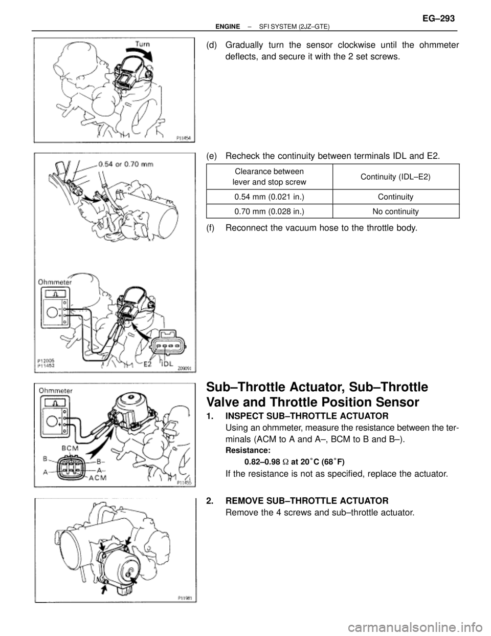
(d) Gradually turn the sensor clockwise until the ohmmeter
deflects, and secure it with the 2 set screws.
(e) Recheck the continuity between terminals IDL and E2.
����������� �
���������� �����������
Clearance between
lever and stop screw������������ �
����������� ������������Continuity (IDL±E2)
����������� �����������0.54 mm (0.021 in.)������������ ������������Continuity
����������� �����������0.70 mm (0.028 in.)������������ ������������No continuity
(f) Reconnect the vacuum hose to the throttle body.
Sub±Throttle Actuator, Sub±Throttle
Valve and Throttle Position Sensor
1. INSPECT SUB±THROTTLE ACTUATOR
Using an ohmmeter, measure the resistance between the ter-
minals (ACM to A and A±, BCM to B and B±).
Resistance:
0.82±0.98 � at 20°C (68°F)
If the resistance is not as specified, replace the actuator.
2. REMOVE SUB±THROTTLE ACTUATOR
Remove the 4 screws and sub±throttle actuator.
± ENGINESFI SYSTEM (2JZ±GTE)EG±293
Page 1585 of 2543
(d) Connect the tester probe of an ohmmeter to the terminals IDL
and E2 of the sensor.
(e) Gradually turn the sensor clockwise until the ohmmeter
deflects, and secure it with the 2 set screws.
(f) Recheck the continuity between terminals IDL and E2.
����������� �
���������� �����������
Clearance between
lever and stop screw������������ �
����������� ������������Continuity (IDL±E2)
����������� �����������0.41 mm (0.016 in.)������������ ������������Continuity
����������� �����������0.48 mm (0.019 in.)������������ ������������No continuity
6. REINSTALL SUB±THROTTLE ACTUATOR
Install the sub±throttle actuator with the 4 screws.
± ENGINESFI SYSTEM (2JZ±GTE)EG±295
 Turn the crankshaft pulley, and align its groove with timing
mark ºOº of the No.1 timing belt cover.
NOTICE: Always turn the crankshaft clockwise.
(b)")
 Insert a 0.50 mm (0.020 in.) feeler gauge between the throttle
stop screw and stop lever.
(c) Connect the tester probe of an ohmmeter to the terminals IDL
and E2 of the sensor.
(d) Gradually tur")
 Connect the tester probe of an ohmmeter to the terminals IDL
and E2 of the sensor.
(e) Gradually turn the sensor clockwise until the ohmmeter
deflects, and secure it with the 2 set screws.
(f)")