Page 23 of 2543
ConditionStandard ValueSymbolTerminal
No.Tester
ConnectionWiring
Color
A C AMPLIFIER TERMINAL STANDARD VALUE
± AIR CONDITIONING SYSTEMTROUBLESHOOTINGAC±23
Page 24 of 2543
Terminal
No.SymbolTester
ConnectionWiring
ColorConditionStandard Value
* After 15 minutes, ON mode will change to OFF mode automatically. AC±24
± AIR CONDITIONING SYSTEMTROUBLESHOOTING
Page 53 of 2543
INSPECTION PROCEDURE
Remove the A/C amplifier with connector still con-
ected.
Measure voltage between terminal + B of air condi-
tioner control assembly connector and body ground.
Voltage: Battery positive voltage
Proceed to next circuit inspection shown on matrix
chart (See page AC±26).
Remove ECU±B fuse from J/B No. 1.
Check continuity of ECU±B fuse.
Continuity
Check ECU±B fuse.
Check for short in all the harness and compo-
nents to the ECU±B fuse (See attached wiring
diagram).
Check voltage between terminal +B of A/C amplifier connector and
body ground.
Check and repair harness and connector between
A/C amplifier and battery.
± AIR CONDITIONING SYSTEMTROUBLESHOOTINGAC±53
Page 55 of 2543
Check continuity between terminal GND of A/C amplifier and body
ground.
Measure resistance between terminal GND of A/C
amplifier and body ground.
Remove HTR fuse from J/B No. 1.
Check continuity of HTR fuse.
Continuity
Check for short in all the harness and compo-
nents to the HTR fuse (See attached wiring
diagram).
Check and repair harness and connector between
A/C amplifier and battery.
Check HTR fuse.
Repair or replace harness or connector.
Resistance: O �� �continuity)
± AIR CONDITIONING SYSTEMTROUBLESHOOTINGAC±55
Page 57 of 2543
INSPECTION PROCEDURE
Check voltage between terminal ACC of A/C amplifier connector and
body ground.
Remove the A/C amplifier with connector still connected
Voltage: Battery positive voltage
1. Turn ignition switch To ACC.
2. Measure voltage between terminals ACC of A/C
amplifier connector and body ground.
Remove CIG fuse from J/B No. 1.
Check continuity of CIG fuse.
Continuity
Proceed to next circuit inspection shown on matrix
chart (See page AC±26).
Check CIG fuse.
Check for short in all the harness and compo-
nents to the CIG fuse (See attached wiring
diagram).
Check and repair harness and connector between
A/C amplifier and battery.
± AIR CONDITIONING SYSTEMTROUBLESHOOTINGAC±57
Page 59 of 2543

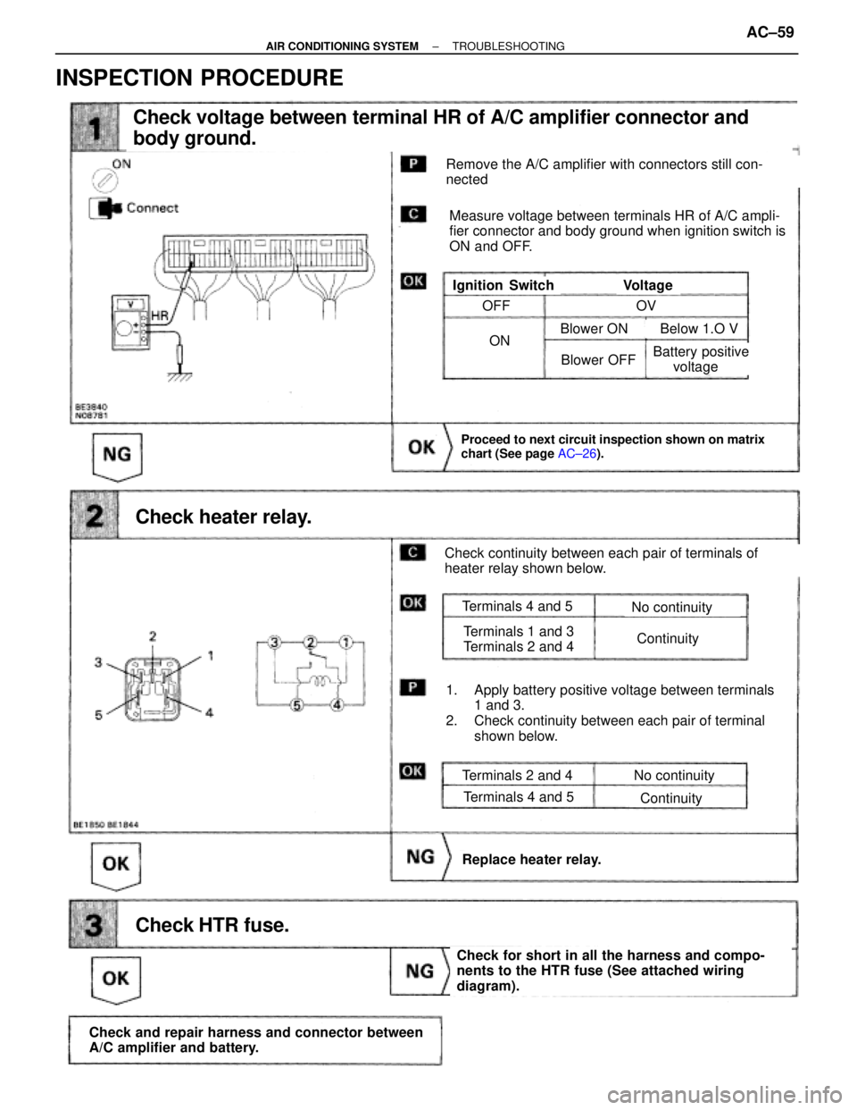
Check voltage between terminal HR of A/C amplifier connector and
body ground.
Check heater relay.
Proceed to next circuit inspection shown on matrix
chart (See page AC±26).
Check HTR fuse.
Check and repair harness and connector between
A/C amplifier and battery.
Check for short in all the harness and compo-
nents to the HTR fuse (See attached wiring
diagram).
Replace heater relay.
Remove the A/C amplifier with connectors still con-
nected
Measure voltage between terminals HR of A/C ampli-
fier connector and body ground when ignition switch is
ON and OFF.
VoltageIgnition Switch
Check continuity between each pair of terminals of
heater relay shown below.
1. Apply battery positive voltage between terminals
1 and 3.
2. Check continuity between each pair of terminal
shown below.
Terminals 2 and 4
Terminals 4 and 5
No continuity
Continuity
Terminals 4 and 5
Terminals 1 and 3
Terminals 2 and 4
No continuity
Continuity
OFF
ON
OV
Blower OFF
Blower ON Below 1.O V
Battery positive
voltage
INSPECTION PROCEDURE
± AIR CONDITIONING SYSTEMTROUBLESHOOTINGAC±59
Page 115 of 2543

INTRODUCTIONGENERAL REPAIR INSTRUCTIONS -
IN-4
GENERAL REPAIR INSTRUCTIONS
1. Use fender, seat and floor covers to keep the vehicle
clean and prevent damage.
2. During disassembly, keep parts in the appropriate order
to facilitate reassembly.
3. Observe the following:
(a) Before performing electrical work, disconnect the
negative cable from the battery terminal.
(b) If it is necessary to disconnect the battery for inspec-
tion or repair, always disconnect the cable from the
negative (-) terminal which is grounded to the ve-
hicle body.
(c) To prevent damage to the battery terminal post, loos-
en the terminal nut and raise the cable straight up
without twisting or prying it.
(d) Clean the battery terminal posts and cable terminals
with a clean shop rag. Do not scrape them with a file
or other abrasive objects.
(e) Install the cable terminal to the battery post with the
nut loose, and tighten the nut after installation. Do
not use a hammer to tap the terminal onto the post.
(f) Be sure the cover for the positive (+) terminal is prop-
erly in place.
4. Check hose and wiring connectors to make sure that they
are secure and correct.
5. Non-reusable parts
(a) Always replace cotter pins, gaskets, O-rings and oil
seals etc. with new ones.
(b) Non-reusable parts are indicated in the component
illustrations by the º�º symbol.
6. Precoated parts
Precoated parts are bolts and nuts, etc. that are coated
with a seal lock adhesive at the factory.
(a) If a precoated part is retightened, loosened or
caused to move in any way, it must be recoated with
the specified adhesive.
(b) When reusing precoated parts, clean off the old
adhesive and dry with compressed air. Then applyIN022-02
Page 132 of 2543

A340E (2JZ-GTE) AUTOMATIC TRANSMISSIONSERVICE SPECIFICATIONS -
AT-26
TORQUE SPECIFICATIONS
Part tightenedN´mkgf´cmft´lbf
Engine x Transmissin6465047
Rear support member x Body2526019
Transmission housing x Transmisson case 14 mm
17 mm34
57345
58025
42
Extension housing x Transmission case3434525
Packing lock pawl bracket77565 in.´lbf
O/D support x Transmission case2526019
Oil pump x Transmission case2121516
Oil pump body x Stator shaft101007
Valve body x Transmission case101007
Upper valve body x Lower valve body6.56556 in.´lbf
Detent spring101007
Oil strainer101007
Oil pan77565 in.´lbf
No. 1 Vehicle speed sensor1616012
No. 2 Vehicle speed sensor5.45548 in.´lbf
Solenoid wiring stopper plate5.45548 in.´lbf
O/D direct clutch vehicle speed sensor5.45548 in.´lbf
Transmission output flange123125090
Throttle cable x Transmission case5.45548 in.´lbf
Union2930022
Cooler pipe union nut3435025
Park/Neutral position switch Bolt
Nut13
6.9130
709
61 in.´lbf
Control shaft lever1616012
AT0F1-05