Page 162 of 2543
 AUTOMATIC TRANSMISSIONCOMPONENT PARTS REMOVAL -
AT-14
12. INSTALL TRANSMISSION CASE
Install the transmission case on the overhaul attachment.
13. REMOVE OIL PAN
NOTICE: Do not turn th")
A340E (2JZ-GTE) AUTOMATIC TRANSMISSIONCOMPONENT PARTS REMOVAL -
AT-14
12. INSTALL TRANSMISSION CASE
Install the transmission case on the overhaul attachment.
13. REMOVE OIL PAN
NOTICE: Do not turn the transmission over as this will con-
taminate the valve body with any foreign matter at the bot-
tom of the pan.
(a) Remove the 19 bolts.
(b) Insert the blade of SST between the transmission case
and oil pan, cut off applied sealer.
SST 09032-00100
NOTICE: Be careful not to damage the oil pan flange.
14. EXAMINE PARTICLES IN PAN
Remove the magnets and use them to collect steel par-
ticles.
Carefully lock at the foreign matter and particles in the pan
and on the magnets to anticipate the type of wear you will
find in the transmission:
�Steel (magnetic): bearing, gear and clutch plate
wear
�Brass (non-magnetic): bushing wear
15. REMOVE OIL STRAINER
(a) Turn over the transmission.
(b) Remove the 3 bolts holding the oil strainer to the valve
body.
16. REMOVE SOLENOID WIRING
(a) Remove the 2 bolts and the clamp.
Page 163 of 2543
A340E (2JZ-GTE) AUTOMATIC TRANSMISSIONCOMPONENT PARTS REMOVAL -
AT-15
(b) Disconnect the 5 connectors from the solenoids.
(c) Remove the stopper plate from the case.
(d) Pull the wiring out of the transmission case.
(e) Remove the O-ring from the grommet.
17. REMOVE VALVE BODY
(a) Remove the 20 bolts.
(b) Remove the valve body.
18. REMOVE CHECK BALL BODY
Remove the check ball body and spring.
19. REMOVE ACCUMULATOR SPRINGS AND PISTONS
(a) Applying compressed air to the oil hole, remove the B
2
and C2 accumulator pistons and 3 springs.
(b) Remove the O-rings from each piston.
Page 252 of 2543
A340E (2JZ-GTE) AUTOMATIC TRANSMISSIONCOMPONENT PARTS INSTALLATION -
AT-104
32. INSTALL VALVE BODY
(a) Align the groove of the manual valve to the pin of the lever.
(b) Install the 20 bolts.
Torque: 10 N´m (100 kgf´cm, 7 ft´lbf)
HINT: Each bolt length (mm, in.) is indicated in the illustra-
tion.
33. INSTALL SOLENOID WIRING
(a) Coat a new O-ring with ATF and install it to the solenoid
wire.
(b) Install the solenoid wiring to the case and install the stop-
per plate.
Torque: 5.4 N´m (55 kgf´cm, 48 in.´lbf)
(c) Connect the 5 solenoid connectors.
(d) Install the clamp with 2 bolts.
Page 283 of 2543
A340E(Others) AUTOMATIC TRANSMISSIONCOMPONENT PARTS REMOVAL -
AT-26
19. REMOVE SOLENOID WIRING
(a) Disconnect the 3 connectors from No.1, No.2 and lock-
up solenoids.
(b) Remove the bolt and stopper plate from the case.
(c) Pull out the solenoid wiring form the transmission case.
(d) Remove the O-rings from the grommet.
20. REMOVE VALVE BODY
(a) Remove the 17 bolts.
(b) Disconnect the throttle cable from the cam and remove
the valve body.
21. REMOVE CHECK BALL BODY, ACCUMULATOR
SPRINGS AND PISTONS
(a) Remove the check ball body and spring.
Page 380 of 2543
A340E(Others) AUTOMATIC TRANSMISSIONCOMPONENT PARTS INSTALLATION -
AT-123
30. INSTALL CHECK BALL BODY AND SPRING
31. INSTALL VALVE BODY
(a) Align the groove of the manual valve to pin of the lever.
(b) Connect the throttle cable to the cam.
(c) Confirm the springs into the accumulator pistons are
installed correctly.
(d) Install the 17 bolts.
HINT: Each bolt length is indicated in the illustration.
Torque: 10 N´m (100 kgf´cm, 7 ft´lbf)
32. INSTALL SOLENOID WIRING
(a) Coat a new O-ring with ATF and install it to the grommet.
(b) Install the solenoid wiring to the case and install the stop-
per plate.
AT0SM-01
Page 414 of 2543
SHIFT LOCK SYSTEM
COMPONENT PARTS LOCATION
WIRING DIAGRAM
AT1±28± AT340E (2JZ±GE) AUTOMATIC TRANSMISSIONSHIFT LOCK SYSTEM
Page 442 of 2543
, B = (E9)������ �
����� ������Terminals
����� �
���� �����Symbols
������ �
����� ������Wiring
Color������������������ �
����������������� ������������������C")
STANDARD VALUE OF ECM TERMINAL
* A = (E10), B = (E9)������ �
����� ������Terminals
����� �
���� �����Symbols
������ �
����� ������Wiring
Color������������������ �
����������������� ������������������Condition
����� �
���� �����Standard
Value
������ ������B76 ± B69����� �����NSW±E1������ ������B±WeBR����� �����IG ON�������������� ��������������Shift Lever; P or N position����� �����Below 3 V
������ ������B76 ± B69����� �����NSW ± E1������ ������B±W eBR����� �����IG ON�������������� ��������������Shift Lever; Other than P or N position����� �����9 ± 14 V
������ ������B3 ± B23����� �����SP2± ± SP2+������ ������G eR������������������ ������������������IG OFF����� �����560 ± 680 �
�����������������������������������IG OFF�����10 ± 16 ������� ������B10 ± B69����� �����S1 ± E1������ ������W±R eBR������������������ ������������������Vehicle driving in 2nd gear position����� �����9 ± 14 ������� ����������� ����������� ������������������������ ������������������IG ON����� �����9 ± 14 ������� ����������� ����������� ������������������������ ������������������IG OFF����� �����10 ± 16 �
������ ������B9 ± B69����� �����S2 ± E1������ ������RL eBR������������������ ������������������Vehicle driving in 2nd or 3rd position����� �����9 ± 14 �
������ ����������� ����������� ����������� �����IG ON�������������� ������������������� �����Below 1.5 V
������ ������B43 ± B65����� �����VTA1±E2������ ������YeBR±B����� �����IG ON�������������� ��������������Accel. pedal is not depressed����� �����Below 0.8 V
������ ������B43 ± B65����� �����VTA1 ± E2������ ������Y eBR±B����� �����IG ON�������������� ��������������Accel. pedal is fully depressed����� �����3.2 ± 4.9 V
������B64 ± B65�����IDL1 ± E2������ReBR±B�����IG ON��������������Accel. pedal is not depressed�����Below 3 V������ ������B64 ± B65����� �����IDL1 ± E2������ ������R eBR±B����� �����IG ON�������������� ��������������Accel. pedal is depressed����� �����9 ± 14 V������ �
����� ������A2 ± B65
����� �
���� �����SP1 ± E2
������ �
����� ������P eBR±B
������������������ �
����������������� ������������������Ignition switch ON
Turn the rear wheel slowly����� �
���� �����Repeat 0±8V
or above
������ ������
A3 ± B69
����� �����
KD±E1
������ ������
YeBR
����� �����
IG ON
�������������� ��������������Kick±down SW; OFF
(Accel. pedal is not depressed)����� �����9 ± 14 V
������ �
����� ������
A3 ± B69����� �
���� �����
KD ± E1������ �
����� ������
Y eBR����� �
���� �����
IG ON�������������� �
������������� ��������������Kick±down SW; ON
(Accel. pedal is fully depressed)����� �
���� �����Below 3 V
������ ������A9 ± B69����� �����2±E1������ ������LG±ReBR����� �����IG ON�������������� ��������������Shift Position; 2 position����� �����7.5 ± 14 V
������ ������A9 ± B69����� �����2 ± E1������ ������LG±R eBR����� �����IG ON�������������� ��������������Shift Position; Other than 2 position����� �����Below 1.5 V
������ ������A10 ± B69����� �����L±E1������ ������G±BeBR����� �����IG ON�������������� ��������������Shift Position; L position����� �����7.5 ± 14 V
������
A10 ± B69
�����
L ± E1
������
G±B eBR
�����
IG ON
��������������Shift Position; Other than L position�����Below 1.5 V������ ������A12 ± B69����� �����OD1 ± E1������ ������BR±B eBR������������������ ������������������Ignition switch ON����� �����4.5 ± 5.5 V������ ������
A18 ± B69
����� �����
M±E1
������ ������
G±YeBR
����� �����
IG ON
�������������� ��������������Pattern select SW: MANU����� �����7.5 ± 14 V
������ ������A18 ± B69����� �����M ± E1������ ������G±Y eBR����� �����IG ON�������������� ��������������Pattern select SW: NORM����� �����Below 1.5 V
������ ������A28 ± B69����� �����OD2±E1������ ������V±GeBR����� �����IG ON�������������� ��������������O/D main SW; ON����� �����7.5 ± 14 V
������ ������A28 ± B69����� �����OD2 ± E1������ ������V±G eBR����� �����IG ON�������������� ��������������O/D main SW; OFF����� �����Below 3 V
������ ������B24 ± B65����� �����OIL ± E2������ ������BR±B eO������������������ ������������������A/T fluid temperature 110°C (230°F)����� �����Below 1 V
AT1±56± AT340E (2JZ±GE) AUTOMATIC TRANSMISSIONTROUBLESHOOTING
Page 456 of 2543
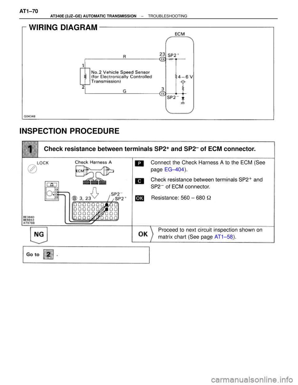
WIRING DIAGRAM
INSPECTION PROCEDURE
Connect the Check Harness A to the ECM (See
page EG±404).
Check resistance between terminals SP2+ and
SP2
- of ECM connector.
Resistance: 560 ± 680 �
Proceed to next circuit inspection shown on
matrix chart (See page AT1±58).
Check resistance between terminals SP2+ and SP2± of ECM connector.
AT1±70± AT340E (2JZ±GE) AUTOMATIC TRANSMISSIONTROUBLESHOOTING
 AUTOMATIC TRANSMISSIONCOMPONENT PARTS REMOVAL -
AT-15
(b) Disconnect the 5 connectors from the solenoids.
(c) Remove the stopper plate from the case.
(d) Pull the wiring out of the t")
 AUTOMATIC TRANSMISSIONCOMPONENT PARTS INSTALLATION -
AT-104
32. INSTALL VALVE BODY
(a) Align the groove of the manual valve to the pin of the lever.
(b) Install the 20 bolts.
Torque:")
 AUTOMATIC TRANSMISSIONCOMPONENT PARTS REMOVAL -
AT-26
19. REMOVE SOLENOID WIRING
(a) Disconnect the 3 connectors from No.1, No.2 and lock-
up solenoids.
(b) Remove the bolt and stopper")
 AUTOMATIC TRANSMISSIONCOMPONENT PARTS INSTALLATION -
AT-123
30. INSTALL CHECK BALL BODY AND SPRING
31. INSTALL VALVE BODY
(a) Align the groove of the manual valve to pin of the lever.
(")
 AUTOMATIC TRANSMISSIONSHIFT LOCK SYSTEM")