Page 53 of 2543
INSPECTION PROCEDURE
Remove the A/C amplifier with connector still con-
ected.
Measure voltage between terminal + B of air condi-
tioner control assembly connector and body ground.
Voltage: Battery positive voltage
Proceed to next circuit inspection shown on matrix
chart (See page AC±26).
Remove ECU±B fuse from J/B No. 1.
Check continuity of ECU±B fuse.
Continuity
Check ECU±B fuse.
Check for short in all the harness and compo-
nents to the ECU±B fuse (See attached wiring
diagram).
Check voltage between terminal +B of A/C amplifier connector and
body ground.
Check and repair harness and connector between
A/C amplifier and battery.
± AIR CONDITIONING SYSTEMTROUBLESHOOTINGAC±53
Page 55 of 2543
Check continuity between terminal GND of A/C amplifier and body
ground.
Measure resistance between terminal GND of A/C
amplifier and body ground.
Remove HTR fuse from J/B No. 1.
Check continuity of HTR fuse.
Continuity
Check for short in all the harness and compo-
nents to the HTR fuse (See attached wiring
diagram).
Check and repair harness and connector between
A/C amplifier and battery.
Check HTR fuse.
Repair or replace harness or connector.
Resistance: O �� �continuity)
± AIR CONDITIONING SYSTEMTROUBLESHOOTINGAC±55
Page 57 of 2543
INSPECTION PROCEDURE
Check voltage between terminal ACC of A/C amplifier connector and
body ground.
Remove the A/C amplifier with connector still connected
Voltage: Battery positive voltage
1. Turn ignition switch To ACC.
2. Measure voltage between terminals ACC of A/C
amplifier connector and body ground.
Remove CIG fuse from J/B No. 1.
Check continuity of CIG fuse.
Continuity
Proceed to next circuit inspection shown on matrix
chart (See page AC±26).
Check CIG fuse.
Check for short in all the harness and compo-
nents to the CIG fuse (See attached wiring
diagram).
Check and repair harness and connector between
A/C amplifier and battery.
± AIR CONDITIONING SYSTEMTROUBLESHOOTINGAC±57
Page 59 of 2543

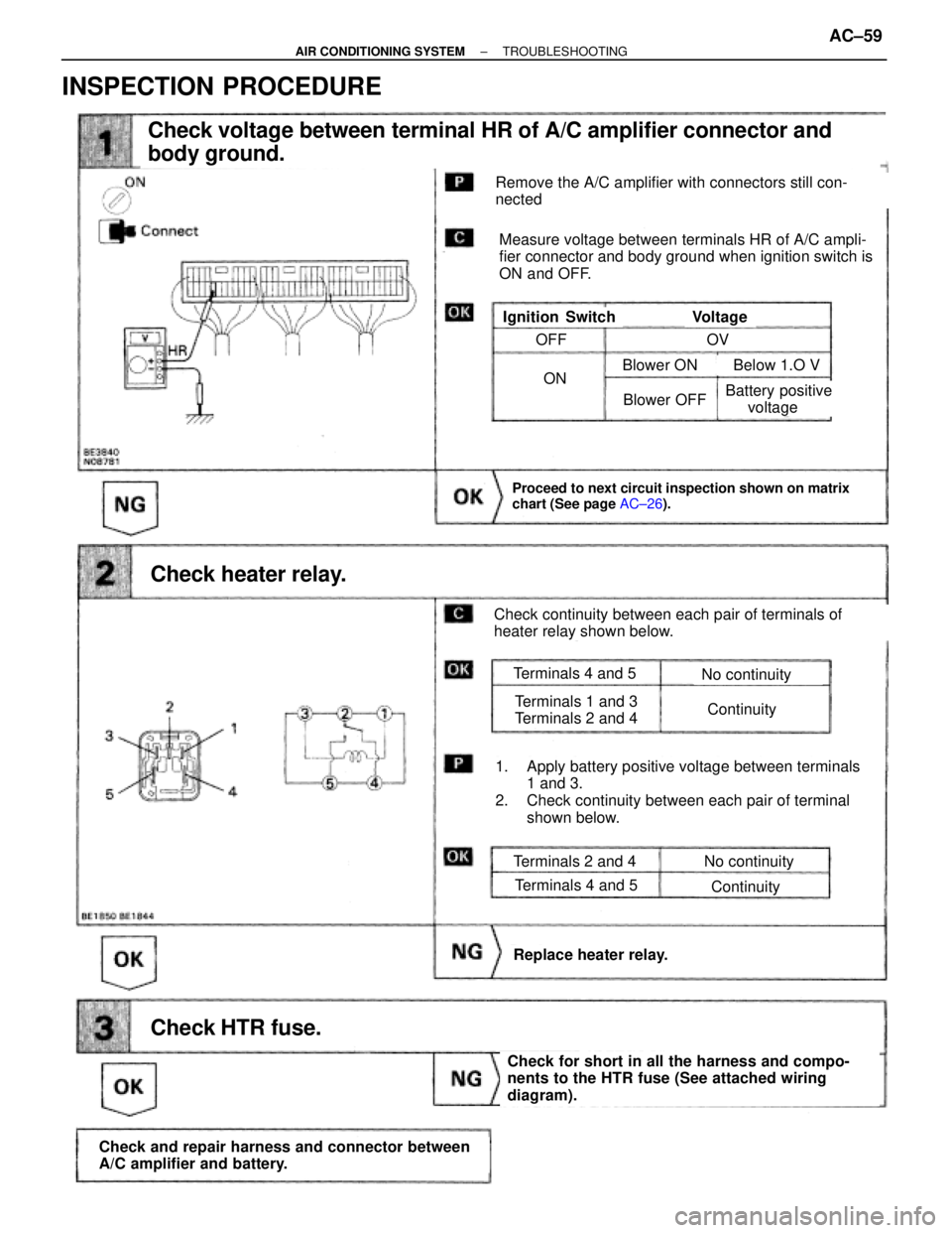
Check voltage between terminal HR of A/C amplifier connector and
body ground.
Check heater relay.
Proceed to next circuit inspection shown on matrix
chart (See page AC±26).
Check HTR fuse.
Check and repair harness and connector between
A/C amplifier and battery.
Check for short in all the harness and compo-
nents to the HTR fuse (See attached wiring
diagram).
Replace heater relay.
Remove the A/C amplifier with connectors still con-
nected
Measure voltage between terminals HR of A/C ampli-
fier connector and body ground when ignition switch is
ON and OFF.
VoltageIgnition Switch
Check continuity between each pair of terminals of
heater relay shown below.
1. Apply battery positive voltage between terminals
1 and 3.
2. Check continuity between each pair of terminal
shown below.
Terminals 2 and 4
Terminals 4 and 5
No continuity
Continuity
Terminals 4 and 5
Terminals 1 and 3
Terminals 2 and 4
No continuity
Continuity
OFF
ON
OV
Blower OFF
Blower ON Below 1.O V
Battery positive
voltage
INSPECTION PROCEDURE
± AIR CONDITIONING SYSTEMTROUBLESHOOTINGAC±59
Page 743 of 2543
(See page IN±30).
Check for short in all the harness and
components connected to the CIG and ECU±IG
fuses (See attached wiring diagram).
(1) Remove instrument panel.
(See BO section)
(2) Disconnect the ECU connector.
(3) Turn ignition switch ON.
Check and replace theft deterrent and door lock
ECU.
Measure voltage between terminal IG and ACC of
theft deterrent ECU connector and body ground.
Voltage: 10 ± 14 V
Check and repair harness and connector between theft deterrent and door lock ECU and battery
(See page IN±30).
Check voltage between terminals IG and ACC of theft deterrent and door
lock ECU and body ground.
Continuity
Remove CIG and ECU±IG fuses from J/B NO. 1.
Check continuity of CIG and ECU±IG fuses.
Check CIG and ECU±IG fuses.
INSPECTION PROCEDURE
± BODY ELECTRICAL SYSTEMBE±141
THEFT DETERRENT AND DOOR LOCK CONTROL SYSTEM
Page 753 of 2543
(See page Be±123).
(See page IN±30).
Remove DOME fuse from R/B No. 2
Repair or replace harness or connector.
Check continuity of DOME fuse.
Continuity
Check for short in all the harness and components
connected to the DOME fuse (See attached wiring
diagram).
Proceed to next circuit inspection shown on matrix
chart (See page BE±123).
(1)Remove the No. 1 under cover and heater duct.
(2)Disconnect the theft deterrent and door lock ECU
connector.
Measure voltage between terminals +B1 and E of
ECU connector.
Check DOME fuse.
Check voltage between terminals +B1 and E of ECU connector.
Check for open in harness and connector between ECU and body ground
(See page IN±30).
Voltage: 10 ± 14 V
Check and repair harness and connector be-
tween ECU and battery.
INSPECTION PROCEDURES
± BODY ELECTRICAL SYSTEMBE±151THEFT DETERRENT AND DOOR LOCK CONTROL SYSTEM
Page 755 of 2543

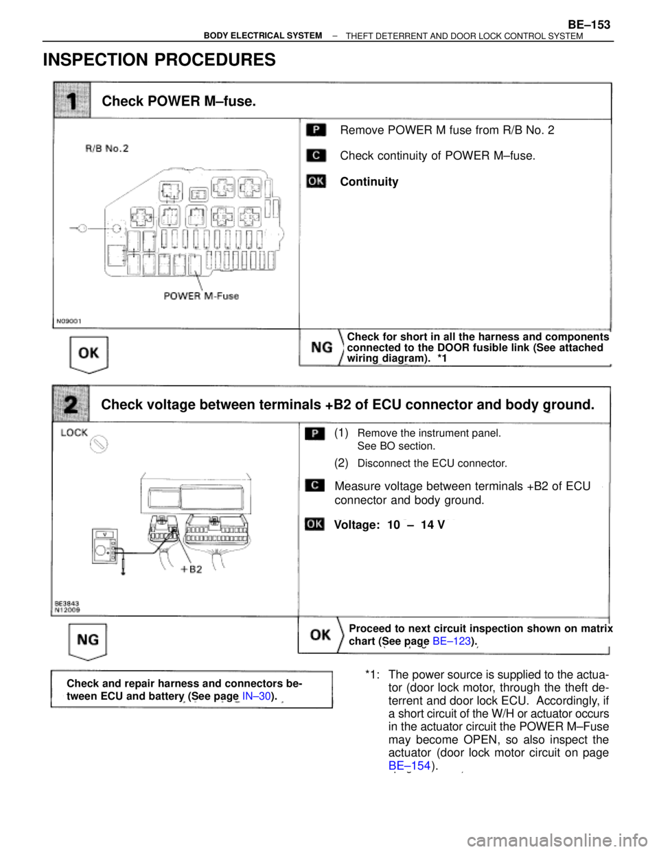
INSPECTION PROCEDURES
(See page BE±123).
page BE±154).
Remove POWER M fuse from R/B No. 2
Check continuity of POWER M±fuse.
Continuity
Check POWER M±fuse.
Check for short in all the harness and components
connected to the DOOR fusible link (See attached
wiring diagram). *1
Proceed to next circuit inspection shown on matrix
chart (See page BE±123).
(1)Remove the instrument panel.
See BO section.
(2)Disconnect the ECU connector.
Measure voltage between terminals +B2 of ECU
connector and body ground.
Check voltage between terminals +B2 of ECU connector and body ground.
Voltage: 10 ± 14 V
*1: The power source is supplied to the actua-
tor (door lock motor, through the theft de-
terrent and door lock ECU. Accordingly, if
a short circuit of the W/H or actuator occurs
in the actuator circuit the POWER M±Fuse
may become OPEN, so also inspect the
actuator (door lock motor circuit on page
BE±154).Check and repair harness and connectors be-
tween ECU and battery (See page IN±30).
± BODY ELECTRICAL SYSTEMBE±153THEFT DETERRENT AND DOOR LOCK CONTROL SYSTEM
Page 784 of 2543
Stop Light Switch Circuit
CIRCUIT DESCRIPTION
When the brake is on, battery voltage normally applies through the stop fuse and stop switch to terminal STP±of
the ECU, and the ECU turns the cruise control off.
A fail±safe function is provided so that cancel functions normally, even if there is a malfunction in the stop light
signal circuit.
(1) If the harness connected to terminal STP±has an open, terminal STP±will have battery positive voltage
and the cruise control will be turned off, also SET not occurring.
(2) If the stop fuse is open, terminal STP + becomes approx.
0 V when the brake is turned on, so the ECU performs cancel function normally.
Also, when the brake is on, the magnetic clutch is cut mechanically by the stop light switch, turning the cruise
control off. (See page BE±173 for operation of the magnetic clutch.)
WIRING DIAGRAM
BE±182± BODY ELECTRICAL SYSTEMCRUISE CONTROL SYSTEM