Page 862 of 2543

SEAT BELT INSPECTION
Emergency Locking Retractor (ELR) and
Automatic Locking Retractor (ALR) type
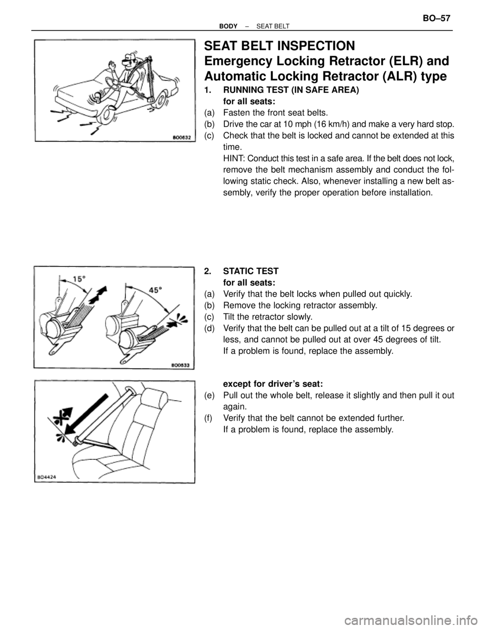
1. RUNNING TEST (IN SAFE AREA)
for all seats:
(a) Fasten the front seat belts.
(b) Drive the car at 10 mph (16 km/h) and make a very hard stop.
(c) Check that the belt is locked and cannot be extended at this
time.
HINT: Conduct this test in a safe area. If the belt does not lock,
remove the belt mechanism assembly and conduct the fol-
lowing static check. Also, whenever installing a new belt as-
sembly, verify the proper operation before installation.
2. STATIC TEST
for all seats:
(a) Verify that the belt locks when pulled out quickly.
(b) Remove the locking retractor assembly.
(c) Tilt the retractor slowly.
(d) Verify that the belt can be pulled out at a tilt of 15 degrees or
less, and cannot be pulled out at over 45 degrees of tilt.
If a problem is found, replace the assembly.
except for driver's seat:
(e) Pull out the whole belt, release it slightly and then pull it out
again.
(f) Verify that the belt cannot be extended further.
If a problem is found, replace the assembly.
± BODYSEAT BELTBO±57
Page 1364 of 2543
4. 2JZ±GTE:
REMOVE ENGINE HANGERS AND GROUND STRAP
5. 2JZ±GTE:
REMOVE CAMSHAFT POSITION SENSORS
6. REMOVE EGR COOLER
7. REMOVE VALVE LIFTERS AND SHIMS
HINT: Store the valve lifters and shims in correct order.
8. REMOVE VALVES
(a) Using SST, compress the valve spring and remove the 2
keepers.
SST 09202±70010
(b) Remove the spring retainer, valve spring, valve and spring
seat.
HINT: Store the valves, valve springs, spring seats and spring
retainers in correct order.
(c) Using needle±nose pliers, remove the oil seal.
CYLINDER HEAD COMPONENTS
INSPECTION AND REPAIR
1. CLEAN TOP SURFACES OF PISTONS AND CYLINDER
BLOCK
(a) Turn the crankshaft, and bring each piston to top dead center
(TDC). Using a gasket scraper, remove all the carbon from
the piston top surface. EG±50
± ENGINEENGINE MECHANICAL
Page 1369 of 2543

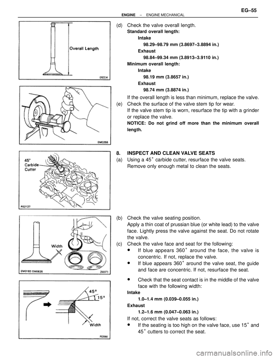
(d) Check the valve overall length.
Standard overall length:
Intake
98.29±98.79 mm (3.8697±3.8894 in.)
Exhaust
98.84±99.34 mm (3.8913±3.9110 in.)
Minimum overall length:
Intake
98.19 mm (3.8657 in.)
Exhaust
98.74 mm (3.8874 in.)
If the overall length is less than minimum, replace the valve.
(e) Check the surface of the valve stem tip for wear.
If the valve stem tip is worn, resurface the tip with a grinder
or replace the valve.
NOTICE: Do not grind off more than the minimum overall
length.
8. INSPECT AND CLEAN VALVE SEATS
(a) Using a 45° carbide cutter, resurface the valve seats.
Remove only enough metal to clean the seats.
(b) Check the valve seating position.
Apply a thin coat of prussian blue (or white lead) to the valve
face. Lightly press the valve against the seat. Do not rotate
the valve.
(c) Check the valve face and seat for the following:
wIf blue appears 360° around the face, the valve is
concentric. If not, replace the valve.
wIf blue appears 360° around the valve seat, the guide
and face are concentric. If not, resurface the seat.
wCheck that the seat contact is in the middle of the valve
face with the following width:
Intake
1.0±1.4 mm (0.039±0.055 in.)
Exhaust
1.2±1.6 mm (0.047±0.063 in.)
If not, correct the valve seats as follows:
wIf the seating is too high on the valve face, use 15° and
45° cutters to correct the seat.
± ENGINEENGINE MECHANICALEG±55
Page 1667 of 2543

POWER STEERING GEAR REMOVAL
1. REMOVE ENGINE UNDER COVER
Remove the 10 screws.
2. REMOVE FR SUSPENSION MEMBER PROTECTOR
Remove the 4 bolts.
3. DISCONNECT INTERMEDIATE SHAFT
(See page SR±15)
4. DISCONNECT RH AND LH TIE ROD ENDS
(See page SA±17)
5. DISCONNECT PRESSURE FEED TUBE
Remove the union bolt and gasket.
6. DISCONNECT RETURN TUBE
Remove the union bolt and 2 gaskets.
7. DISCONNECT PPS SOLENOID CONNECTOR
8. REMOVE RACK HOUSING BRACKET AND GROMMET
Remove the 2 bolts and nuts.
9. REMOVE POWER STEERING GEAR ASSEMBLY
Remove the 2 bolts and nuts.
POWER STEERING GEAR
DISASSEMBLY
NOTICE: When using a vise, do not overtighten it.
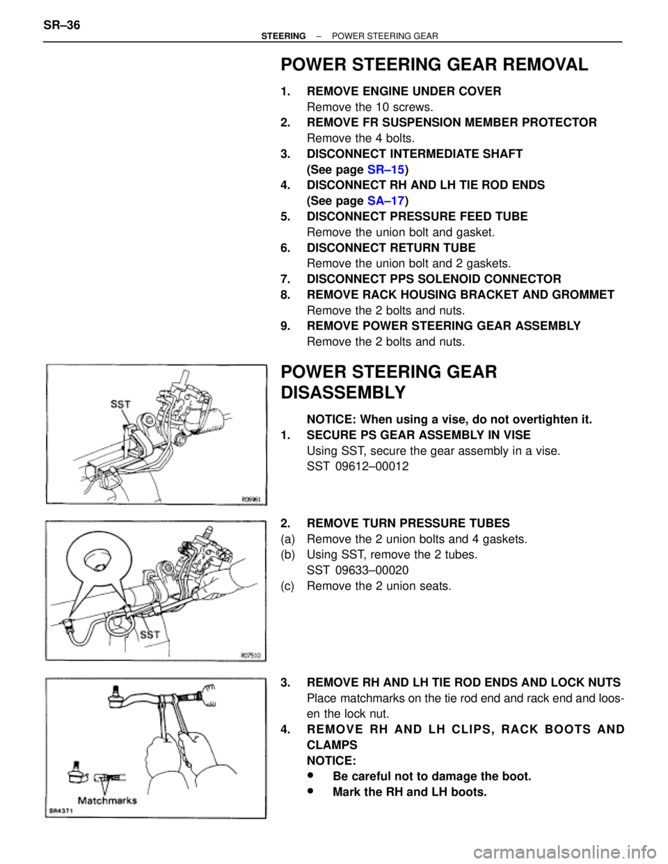
1. SECURE PS GEAR ASSEMBLY IN VISE
Using SST, secure the gear assembly in a vise.
SST 09612±00012
2. REMOVE TURN PRESSURE TUBES
(a) Remove the 2 union bolts and 4 gaskets.
(b) Using SST, remove the 2 tubes.
SST 09633±00020
(c) Remove the 2 union seats.
3. REMOVE RH AND LH TIE ROD ENDS AND LOCK NUTS
Place matchmarks on the tie rod end and rack end and loos-
en the lock nut.
4. REMOVE RH AND LH CLIPS, RACK BOOTS AND
CLAMPS
NOTICE:
wBe careful not to damage the boot.
wMark the RH and LH boots. SR±36
± STEERINGPOWER STEERING GEAR