Page 29 of 2543
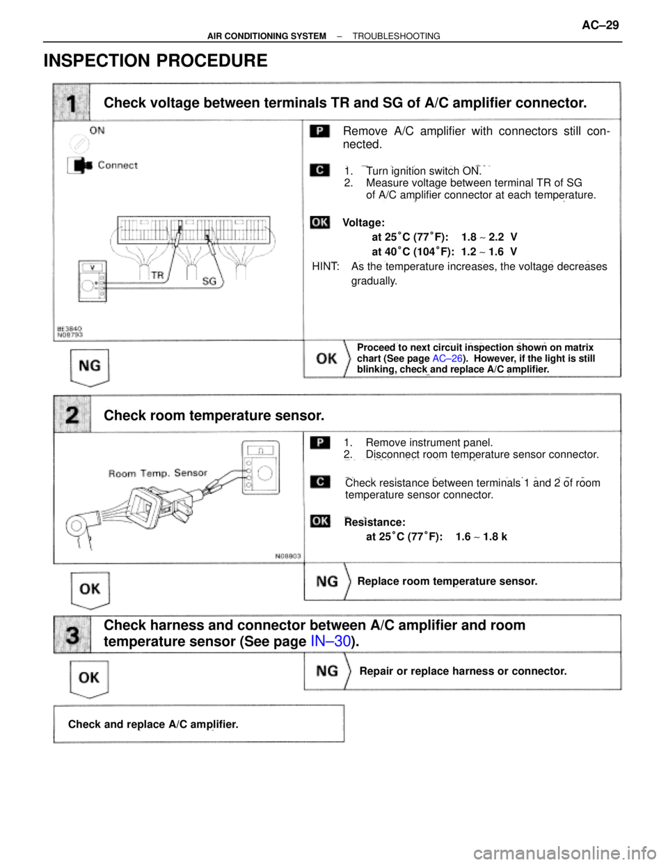
INSPECTION PROCEDURE
Proceed to next circuit inspection shown on matrix
chart (See page AC±26). However, if the light is still
blinking, check and replace A/C amplifier.
(See page IN±30).(See Page IN±30).
Remove A/C amplifier with connectors still con-
nected.
Check voltage between terminals TR and SG of A/C amplifier connector.
Check room temperature sensor.
Check harness and connector between A/C amplifier and room
temperature sensor (See page
IN±30).
Replace room temperature sensor.
Repair or replace harness or connector.
Check and replace A/C amplifier.
1. Turn ignition switch ON.
2. Measure voltage between terminal TR of SG
of A/C amplifier connector at each temperature.
1. Remove instrument panel.
2. Disconnect room temperature sensor connector.
Check resistance between terminals 1 and 2 of room
temperature sensor connector.
Resistance:
at 25°C (77°F): 1.6 ~ 1.8 k�
HINT: As the temperature increases, the voltage decreases
gradually.
Voltage:
at 25°C (77°F): 1.8 ~ 2.2 V
at 40°C (104°F): 1.2 ~ 1.6 V
± AIR CONDITIONING SYSTEMTROUBLESHOOTINGAC±29
Page 43 of 2543
(See page IN±30).
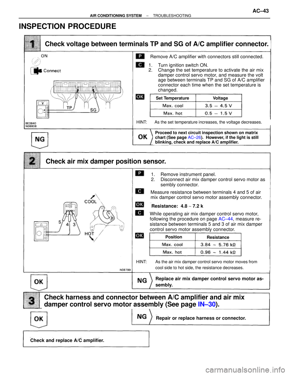
Check voltage between terminals TP and SG of A/C amplifier connector.
Check air mix damper position sensor.
Check and replace A/C amplifier.
Check harness and connector between A/C amplifier and air mix
damper control servo motor assembly (See page IN±30).
Repair or replace harness or connector.
Replace air mix damper control servo motor as-
sembly.
Proceed to next circuit inspection shown on matrix
chart (See page AC±26). However, if the light is still
blinking, check and replace A/C amplifier.
Set TemperatureVoltage
PositionResistance
Remove A/C amplifier with connectors still connected.
1. Turn ignition switch ON.
2. Change the set temperature to activate the air mix
damper control servo motor, and measure the volt
age between terminals TP and SG of A/C amplifier
connector each time when the set temperature is
changed.
HINT: As the set temperature increases, the voltage decreases.
1. Remove instrument panel.
2. Disconnect air mix damper control servo motor as
sembly connector.
Measure resistance between terminals 4 and 5 of air
mix damper control servo motor assembly connector.
While operating air mix damper control servo motor,
following the procedure on page AC±44, measure re-
sistance between terminals 5 and 3 of air mix damper
control servo motor assembly connector.
HINT: As the air mix damper control servo motor moves from
cool side to hot side, the resistance decreases.
Resistance: 4.8 ~ 7.2 k�
INSPECTION PROCEDURE
± AIR CONDITIONING SYSTEMTROUBLESHOOTINGAC±43
Page 47 of 2543
(See page AC±26).
(See page IN±30).
AC±22).
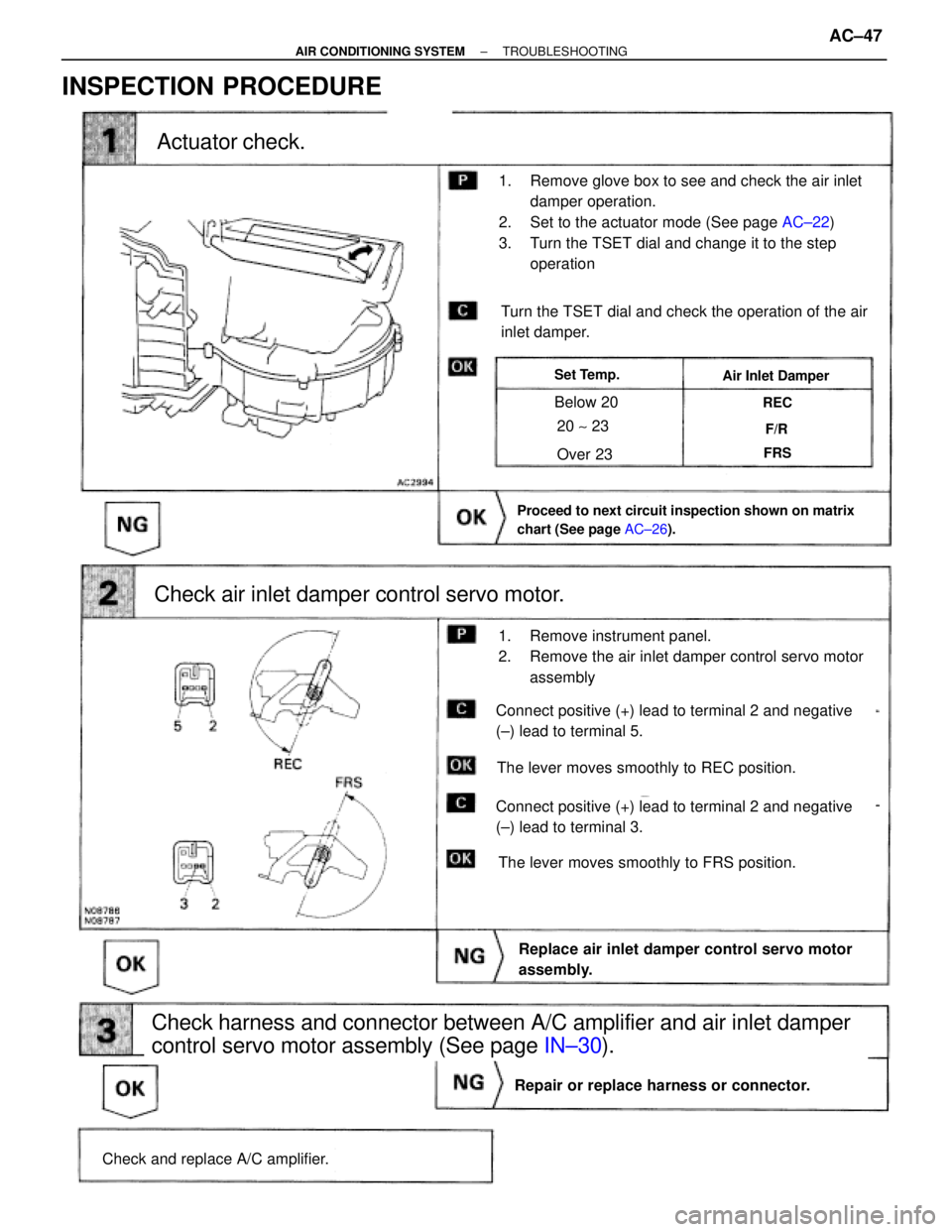
Actuator check.
Check air inlet damper control servo motor.
Check and replace A/C amplifier.
Repair or replace harness or connector.
Replace air inlet damper control servo motor
assembly.
Check harness and connector between A/C amplifier and air inlet damper
control servo motor assembly (See page IN±30).
Proceed to next circuit inspection shown on matrix
chart (See page AC±26).
Turn the TSET dial and check the operation of the air
inlet damper.
The lever moves smoothly to FRS position.
The lever moves smoothly to REC position.
Set Temp.Air Inlet Damper
Below 20
Over 23
20 ~ 23
REC
F/R
FRS
1. Remove glove box to see and check the air inlet
damper operation.
2. Set to the actuator mode (See page AC±22)
3. Turn the TSET dial and change it to the step
operation
1. Remove instrument panel.
2. Remove the air inlet damper control servo motor
assembly
Connect positive (+) lead to terminal 2 and negative
(±) lead to terminal 3.
Connect positive (+) lead to terminal 2 and negative
(±) lead to terminal 5.
INSPECTION PROCEDURE
± AIR CONDITIONING SYSTEMTROUBLESHOOTINGAC±47
Page 49 of 2543
(See page IN±30).
AC±50,
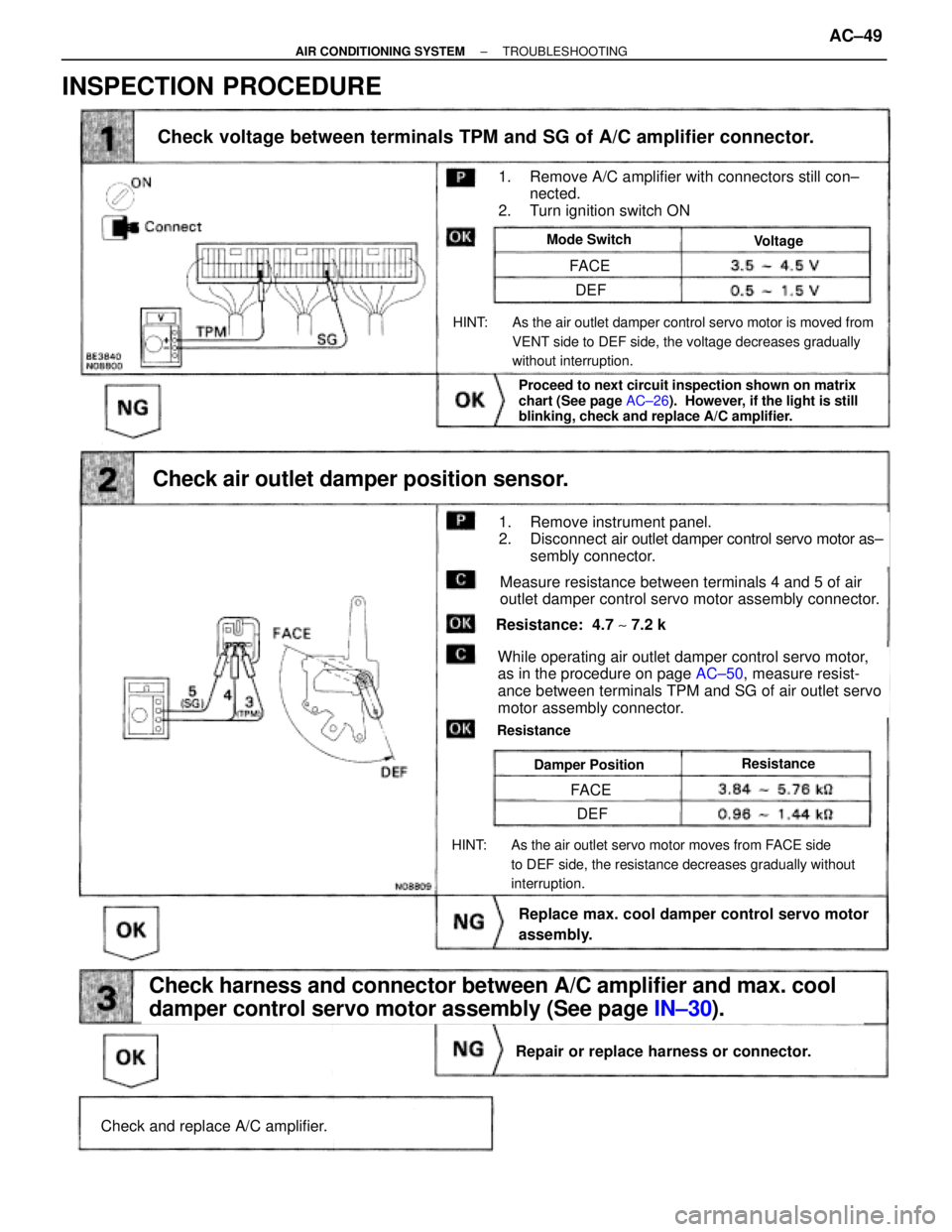
Check voltage between terminals TPM and SG of A/C amplifier connector.
Check and replace A/C amplifier.
Repair or replace harness or connector.
Check harness and connector between A/C amplifier and max. cool
damper control servo motor assembly (See page IN±30).
Replace max. cool damper control servo motor
assembly.
Check air outlet damper position sensor.
Proceed to next circuit inspection shown on matrix
chart (See page AC±26). However, if the light is still
blinking, check and replace A/C amplifier.
ResistanceDamper Position
Resistance: 4.7 ~ 7.2 k�
While operating air outlet damper control servo motor,
as in the procedure on page AC±50, measure resist-
ance between terminals TPM and SG of air outlet servo
motor assembly connector.
Resistance
HINT: As the air outlet servo motor moves from FACE side
to DEF side, the resistance decreases gradually without
interruption.
Measure resistance between terminals 4 and 5 of air
outlet damper control servo motor assembly connector.
1. Remove instrument panel.
2. Disconnect air outlet damper control servo motor as±
sembly connector.
HINT: As the air outlet damper control servo motor is moved from
VENT side to DEF side, the voltage decreases gradually
without interruption.
Mode SwitchVoltage
1. Remove A/C amplifier with connectors still con±
nected.
2. Turn ignition switch ON
FACE
FACE
DEF
DEF
INSPECTION PROCEDURE
± AIR CONDITIONING SYSTEMTROUBLESHOOTINGAC±49
Page 51 of 2543
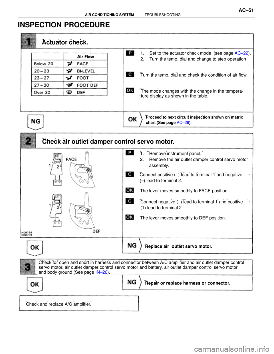
INSPECTION PROCEDURE
AC±22).
Check and replace A/C amplifier.
Repair or replace harness or connector.
Check for open and short in harness and connector between A/C amplifier and air outlet damper control
servo motor, air outlet damper control servo motor and battery, air outlet damper control servo motor
and body ground (See page IN±26).
Replace air outlet servo motor.
Check air outlet damper control servo motor.
Proceed to next circuit inspection shown on matrix
chart (See page AC±26).
Actuator check.
Turn the temp. dial and check the condition of air flow.
The mode changes with the change in the tempera-
ture display as shown in the table.
The lever moves smoothly to DEF position.
The lever moves smoothly to FACE position.
Connect positive (+) lead to terminal 1 and negative
(±) lead to terminal 2.
Connect negative (±) lead to terminal 1 and positive
(1) lead to terminal 2.
1. Remove instrument panel.
2. Remove the air outlet damper control servo motor
assembly.
1. Set to the actuator check mode (see page AC±22).
2. Turn the temp. dial and change to step operation
.
± AIR CONDITIONING SYSTEMTROUBLESHOOTINGAC±51
Page 80 of 2543
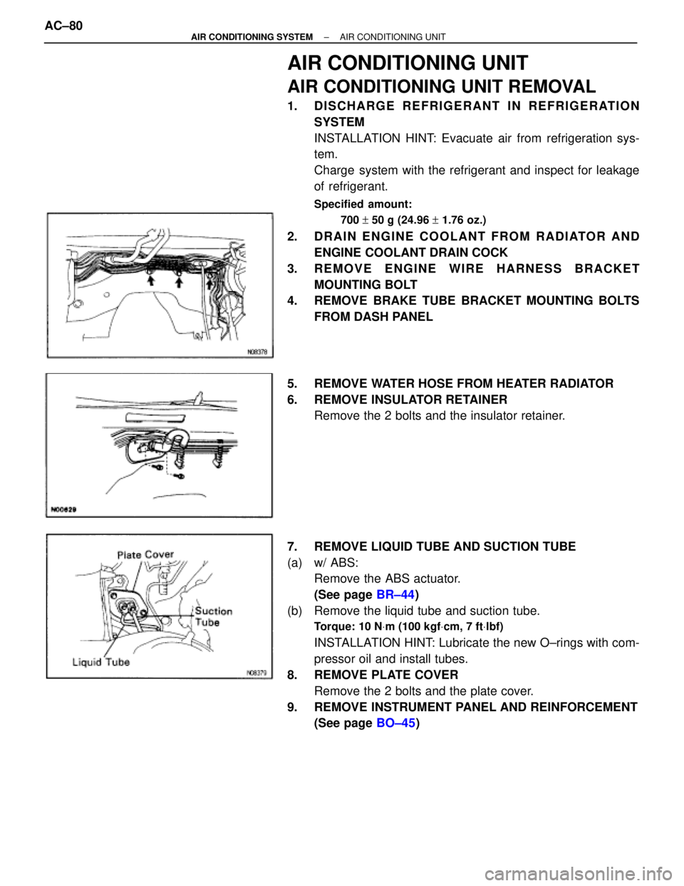
AIR CONDITIONING UNIT
AIR CONDITIONING UNIT REMOVAL
1. DISCHARGE REFRIGERANT IN REFRIGERATION
SYSTEM
INSTALLATION HINT: Evacuate air from refrigeration sys-
tem.
Charge system with the refrigerant and inspect for leakage
of refrigerant.
Specified amount:
700 + 50 g (24.96 + 1.76 oz.)
2. DRAIN ENGINE COOLANT FROM RADIATOR AND
ENGINE COOLANT DRAIN COCK
3. REMOVE ENGINE WIRE HARNESS BRACKET
MOUNTING BOLT
4. REMOVE BRAKE TUBE BRACKET MOUNTING BOLTS
FROM DASH PANEL
5. REMOVE WATER HOSE FROM HEATER RADIATOR
6. REMOVE INSULATOR RETAINER
Remove the 2 bolts and the insulator retainer.
7. REMOVE LIQUID TUBE AND SUCTION TUBE
(a) w/ ABS:
Remove the ABS actuator.
(See page BR±44)
(b) Remove the liquid tube and suction tube.
Torque: 10 NVm (100 kgfVcm, 7 ftVlbf)
INSTALLATION HINT: Lubricate the new O±rings with com-
pressor oil and install tubes.
8. REMOVE PLATE COVER
Remove the 2 bolts and the plate cover.
9. REMOVE INSTRUMENT PANEL AND REINFORCEMENT
(See page BO±45) AC±80
± AIR CONDITIONING SYSTEMAIR CONDITIONING UNIT
Page 101 of 2543
SERVOMOTOR
AIR INLET SERVOMOTOR REMOVAL
1. REMOVE INSTRUMENT PANEL
(See page BO±45)
2. REMOVE AIR INLET SERVOMOTOR
(a) Disconnect the connector.
(b) Disconnect the control link.
(c) Remove the 3 screws and the air inlet servomotor.
AIR INLET SERVOMOTOR INSPECTION
(See page AC±47)
AIR INLET SERVOMOTOR
INSTALLATION
Installation is in the reverse order of removal.
AIR MIX SERVOMOTOR REMOVAL
1. REMOVE INSTRUMENT PANEL
(See page BO±45)
2. REMOVE AIR MIX SERVOMOTOR
(a) Remove the defroster duct.
(b) Remove the 3 screws and the water valve cover.
(c) Disconnect the connector.
(d) Disconnect the control link.
(e) Remove the 2 screws and the air mix servomotor.
AIR MIX SERVOMOTOR INSPECTION
(See page AC±47)
AIR MIX SERVOMOTOR INSTALLATION
Installation is in the reverse order of removal.
± AIR CONDITIONING SYSTEMSERVOMOTORAC±101
Page 102 of 2543
AIR OUTLET SERVOMOTOR REMOVAL
1. REMOVE INSTRUMENT PANEL
(See page BO±45)
2. REMOVE AIR OUTLET SERVOMOTOR
(a) Disconnect the connector.
(b) Remove the 3 screws and the air outlet servomotor.
AIR OUTLET SERVOMOTOR
INSPECTION
(See page AC±51)
AIR OUTLET SERVOMOTOR
INSTALLATION
Installation is in the reverse order of removal. AC±102
± AIR CONDITIONING SYSTEMSERVOMOTOR