Page 116 of 2543

INTRODUCTIONGENERAL REPAIR INSTRUCTIONS -
IN-5
the specified seal lock adhesive to the bolt, nut or
threads.
(c) Precoated parts are indicated in the component il-
lustrations by the º�º symbol.
7. When necessary, use a sealer on gaskets to prevent
leaks.
8. Carefully observe all specifications for bolt tightening
torques. Always use a torque wrench.
9. Use of special service tools (SST) and special service ma-
terials (SSM) may be required, depending on the nature
of the repair. Be sure to use SST and SSM where speci-
fied and follow the proper work procedure. A list of SST
and SSM can be found at the preparation of AT section.
10. When replacing fuses, be sure the new fuse has the cor-
rect amperage rating. DO NOT exceed the rating or use
one with a lower rating.
11. To pull apart electrical connectors, pull on the connector
itself, not the wires.
12. Care must be taken when jacking up and supporting the
vehicle. Be sure to lift and support the vehicle at the prop-
er locations.
(a) If the vehicle is to be jacked up only at the front or
rear end, be sure to block the wheels at the opposite
end in order to ensure safety.
(b) After the vehicle is jacked up, be sure to support it on
stands. It is extremely dangerous to do any work on
a vehicle raised on a jack alone, even for a small job
that can be finished quickly.
Page 743 of 2543
(See page IN±30).
Check for short in all the harness and
components connected to the CIG and ECU±IG
fuses (See attached wiring diagram).
(1) Remove instrument panel.
(See BO section)
(2) Disconnect the ECU connector.
(3) Turn ignition switch ON.
Check and replace theft deterrent and door lock
ECU.
Measure voltage between terminal IG and ACC of
theft deterrent ECU connector and body ground.
Voltage: 10 ± 14 V
Check and repair harness and connector between theft deterrent and door lock ECU and battery
(See page IN±30).
Check voltage between terminals IG and ACC of theft deterrent and door
lock ECU and body ground.
Continuity
Remove CIG and ECU±IG fuses from J/B NO. 1.
Check continuity of CIG and ECU±IG fuses.
Check CIG and ECU±IG fuses.
INSPECTION PROCEDURE
± BODY ELECTRICAL SYSTEMBE±141
THEFT DETERRENT AND DOOR LOCK CONTROL SYSTEM
Page 1041 of 2543

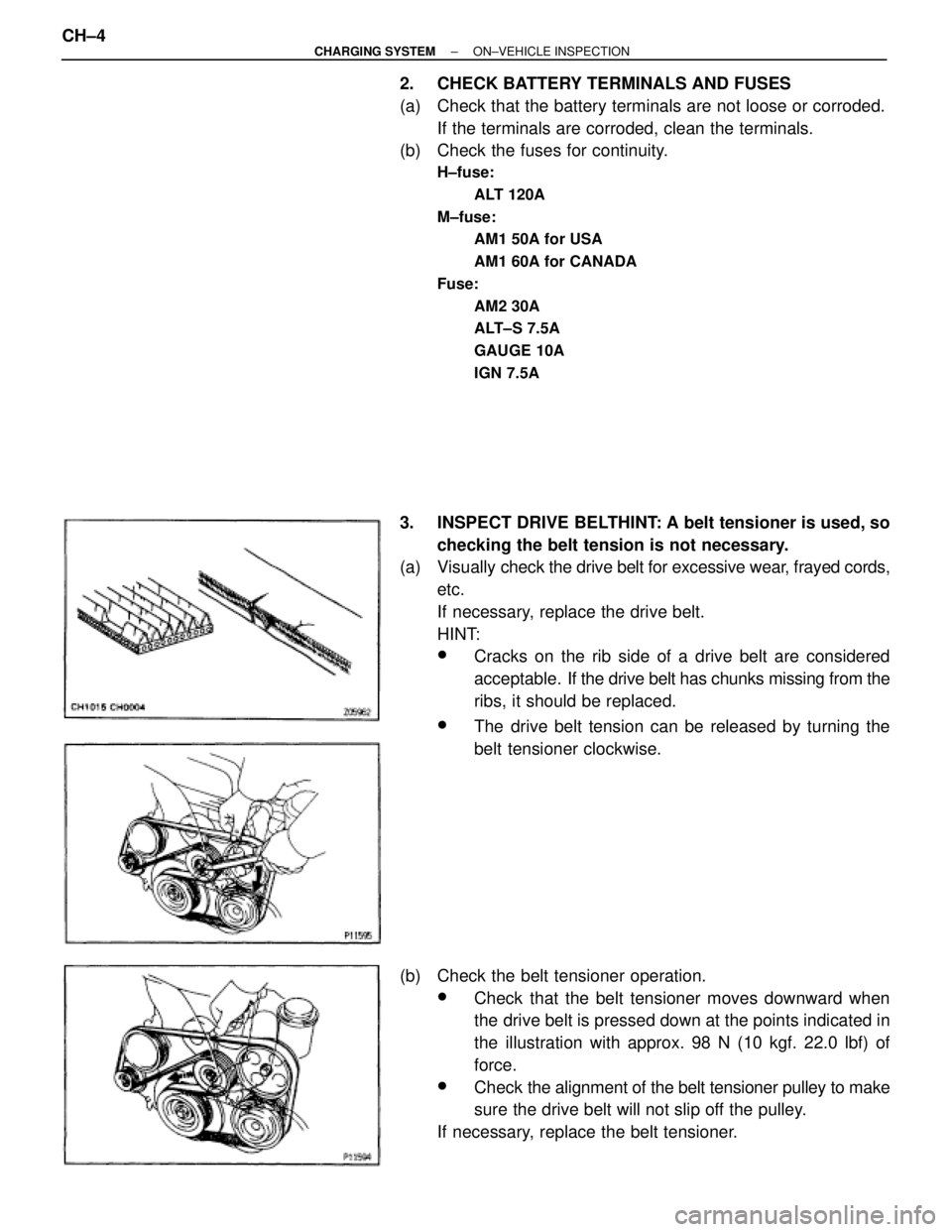
2. CHECK BATTERY TERMINALS AND FUSES
(a) Check that the battery terminals are not loose or corroded.
If the terminals are corroded, clean the terminals.
(b) Check the fuses for continuity.
H±fuse:
ALT 120A
M±fuse:
AM1 50A for USA
AM1 60A for CANADA
Fuse:
AM2 30A
ALT±S 7.5A
GAUGE 10A
IGN 7.5A
3. INSPECT DRIVE BELTHINT: A belt tensioner is used, so
checking the belt tension is not necessary.
(a) Visually check the drive belt for excessive wear, frayed cords,
etc.
If necessary, replace the drive belt.
HINT:
wCracks on the rib side of a drive belt are considered
acceptable. If the drive belt has chunks missing from the
ribs, it should be replaced.
wThe drive belt tension can be released by turning the
belt tensioner clockwise.
(b) Check the belt tensioner operation.
wCheck that the belt tensioner moves downward when
the drive belt is pressed down at the points indicated in
the illustration with approx. 98 N (10 kgf. 22.0 lbf) of
force.
wCheck the alignment of the belt tensioner pulley to make
sure the drive belt will not slip off the pulley.
If necessary, replace the belt tensioner. CH±4
± CHARGING SYSTEMON±VEHICLE INSPECTION
Page 1104 of 2543
ELECTRIC COOLING FAN (2JZ±GTE)
On±Vehicle Inspection
1. C H E C K C O O L I N G FA N O P E R AT I O N W I T H L O W
TEMPERATURE (Below 88°C (190°F))
(a) Turn the ignition switch ON.
(b) Check that the cooling fan stops.
If not, check the cooling fan relay and ECT switch, and check
for a separated connector or severed wire between the No.1
radiator fan relay and ECT switch.
(c) Disconnect the ECT switch connector.
(d) Check that the cooling fan rotates.
If not, check the No.1 radiator relay, No.2 radiator fan relay,
cooling fan, fuses, and check for short circuit between the
No.1 radiator fan relay and ECT switch.
(e) Reconnect the ECT switch connector.
2. CHECK COOLING FAN OPERATION WITH HIGH
TEMPERATURE (Above 97°C (207°F))
(a) Start the engine, and raise coolant temperature to above
97°C (207°F).
(b) Check that the cooling fan rotates.
If not, replace the ECT switch.
± ENGINECOOLING SYSTEMEG±353
Page 1173 of 2543

(b) Wh e n re u sin g pre co a te d pa rts, cle a n off th e old
adhesive and dry with compressed air. Then apply the
specified seal lock adhesive to the bolt, nut or threads.
(c) P re co a te d pa rts are in d ica te d in th e co mponent
illustrations by the º�º symbol.
7. When necessary, use a sealer on gaskets to prevent leaks.
8. Carefully observe all specifications for bolt tightening
torques. Always use a torque wrench.
9. Use of special service tools (SST) and special service
materials (SSM) may be required, depending on the nature
of the repair. Be sure to use SST and SSM where specified
and follow the proper work procedure. A list of SST and SSM
can be found in the preparation part at the front of each
section in this manual.
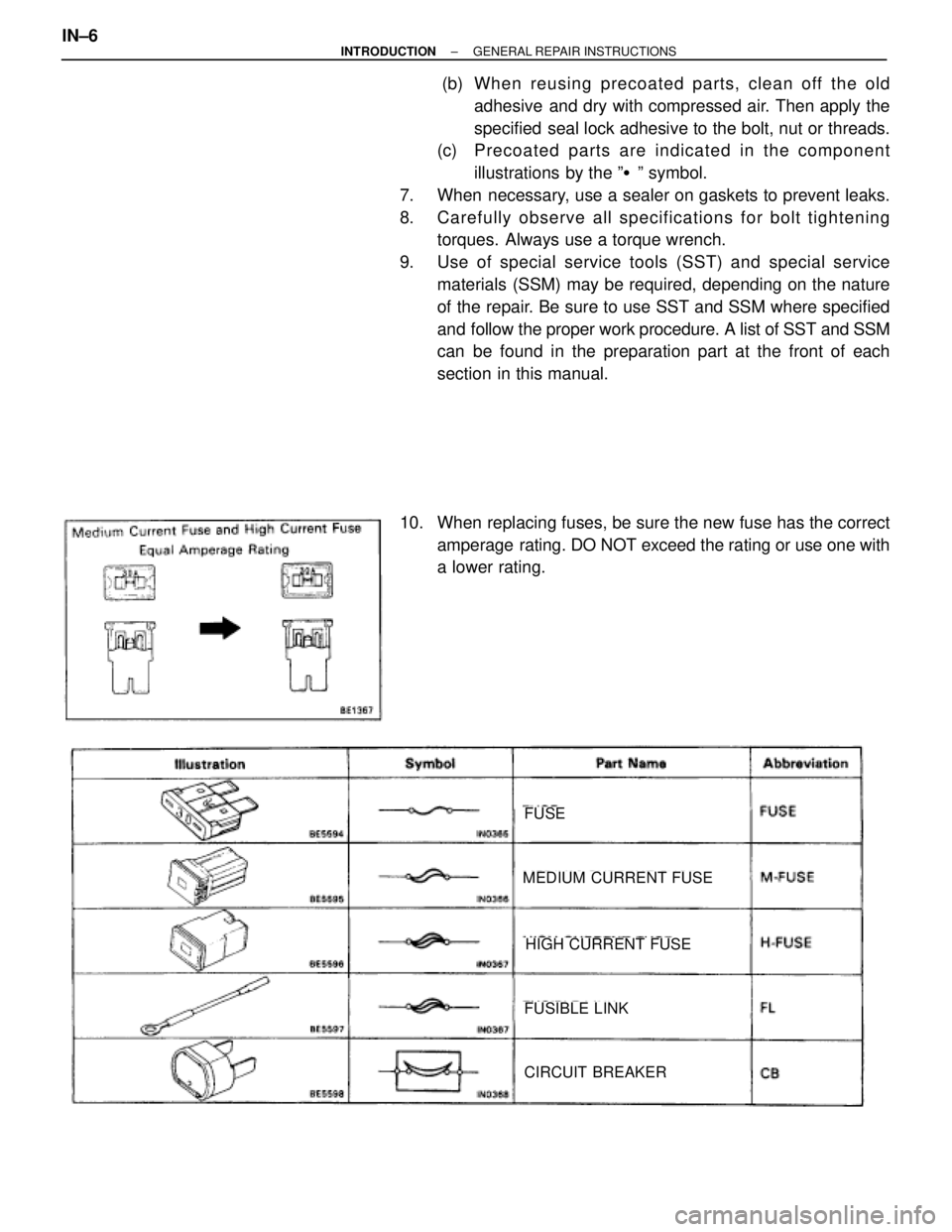
10. When replacing fuses, be sure the new fuse has the correct
amperage rating. DO NOT exceed the rating or use one with
a lower rating.
FUSE
MEDIUM CURRENT FUSE
HIGH CURRENT FUSE
FUSIBLE LINK
CIRCUIT BREAKER
IN±6± INTRODUCTIONGENERAL REPAIR INSTRUCTIONS
Page 1554 of 2543

FUEL PUMP
ON±VEHICLE INSPECTION
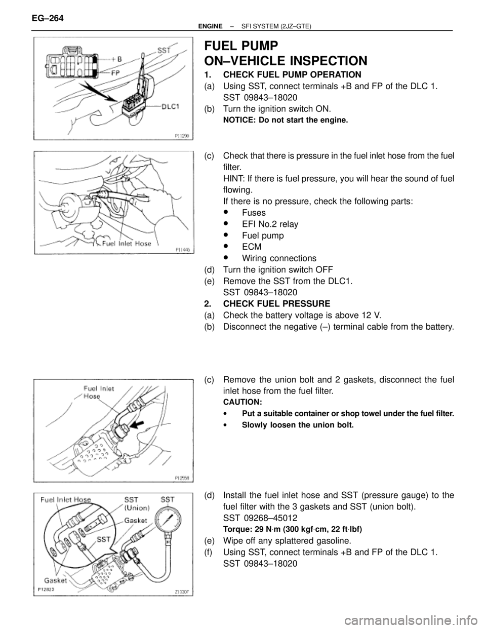
1. CHECK FUEL PUMP OPERATION
(a) Using SST, connect terminals +B and FP of the DLC 1.
SST 09843±18020
(b) Turn the ignition switch ON.
NOTICE: Do not start the engine.
(c) Check that there is pressure in the fuel inlet hose from the fuel
filter.
HINT: If there is fuel pressure, you will hear the sound of fuel
flowing.
If there is no pressure, check the following parts:
wFuses
wEFI No.2 relay
wFuel pump
wECM
wWiring connections
(d) Turn the ignition switch OFF
(e) Remove the SST from the DLC1.
SST 09843±18020
2. CHECK FUEL PRESSURE
(a) Check the battery voltage is above 12 V.
(b) Disconnect the negative (±) terminal cable from the battery.
(c) Remove the union bolt and 2 gaskets, disconnect the fuel
inlet hose from the fuel filter.
CAUTION:
wPut a suitable container or shop towel under the fuel filter.
wSlowly loosen the union bolt.
(d) Install the fuel inlet hose and SST (pressure gauge) to the
fuel filter with the 3 gaskets and SST (union bolt).
SST 09268±45012
Torque: 29 NVm (300 kgfVcm, 22 ftVlbf)
(e) Wipe off any splattered gasoline.
(f) Using SST, connect terminals +B and FP of the DLC 1.
SST 09843±18020 EG±264
± ENGINESFI SYSTEM (2JZ±GTE)