Page 685 of 2543

4. COMPACT DISC PLAYER
Compact Disc (hereafter called ºCDº) Players use a laser
beam pick±up to read the digital signals recorded on the CD
and reproduce analog signals of the music, etc. There are 4.7
in. (12 cm) and 3.2 in. (8 cm) discs in the CD player.
HINT: Never attempt to disassemble or oil any part of the
player unit. Do not insert any object other than a disc into the
magazine.
NOTICE: CD players use an invisible laser beam which
could cause hazardous radiation exposure. Be sure to
operate the player correctly as instructed.
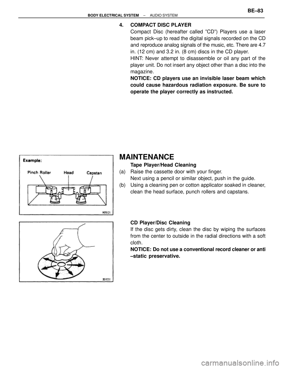
MAINTENANCE
Tape Player/Head Cleaning
(a) Raise the cassette door with your finger.
Next using a pencil or similar object, push in the guide.
(b) Using a cleaning pen or cotton applicator soaked in cleaner,
clean the head surface, punch rollers and capstans.
CD Player/Disc Cleaning
If the disc gets dirty, clean the disc by wiping the surfaces
from the center to outside in the radial directions with a soft
cloth.
NOTICE: Do not use a conventional record cleaner or anti
±static preservative.
± BODY ELECTRICAL SYSTEMAUDIO SYSTEMBE±83
Page 702 of 2543
Function OK if different cassette
tape installed?
Operates normally after cleaning the heads?
(See MAINTENANCE OF TAPE PLAYER)
Cassette tape faulty?
Tape PlayerSOUND QUALITY POOR (VOLUME FAINT)
Tape PlayerTAPE JAMMED, MALFUNCTION WITH TAPE SPEED
OR AUTO REVERSE
Head dirty.
Is radio operating normally?Radio assembly faulty.
Is speaker properly installed?Install properly.
Temporarily install another speaker.
Functions OK?Speaker faulty.
Radio assembly faulty.
Radio assembly or power amplifier faulty.
Functions OK is different tape (less
than 120 mins.) is installed?Cassette tape faulty.
is there a foreign object inside tape player?Remove foreign object.
Operates normally after cleaning the heads?
(See MAINTENANCE OF TAPE PLAYER)Head faulty.
Radio assembly faulty.
BE±100± BODY ELECTRICAL SYSTEMAUDIO SYSTEM
Page 1039 of 2543

EQUIPMENT
������������������ ������������������Battery specific gravity gauge������������������� �������������������Except maintenance±free battery
������������������ ������������������Torque wrench������������������� �������������������
������������������ ������������������Vernier calipers������������������� �������������������Rotor (Slip ring)
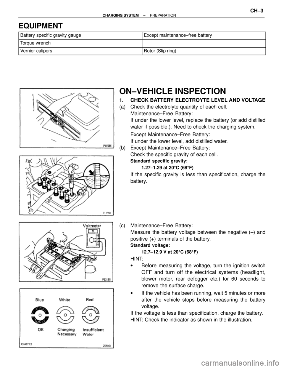
ON±VEHICLE INSPECTION
1. CHECK BATTERY ELECTROYTE LEVEL AND VOLTAGE
(a) Check the electrolyte quantity of each cell.
Maintenance±Free Battery:
If under the lower level, replace the battery (or add distilled
water if possible.). Need to check the charging system.
Except Maintenance±Free Battery:
If under the lower level, add distilled water.
(b) Except Maintenance±Free Battery:
Check the specific gravity of each cell.
Standard specific gravity:
1.27±1.29 at 205C (685F)
If the specific gravity is less than specification, charge the
battery.
(c) Maintenance±Free Battery:
Measure the battery voltage between the negative (±) and
positive (+) terminals of the battery.
Standard voltage:
12.7±12.9 V at 205C (685F)
HINT:
wBefore measuring the voltage, turn the ignition switch
OFF and turn off the electrical systems (headlight,
blower motor, rear defogger etc.) for 60 seconds to
remove the surface charge.
wIf the vehicle has been running, wait 5 minutes or more
after the vehicle stops before measuring the battery
voltage.
If the voltage is less than specification, charge the battery.
HINT: Check the indicator as shown in the illustration.
± CHARGING SYSTEMPREPARATIONCH±3
Page 1040 of 2543

EQUIPMENT
������������������ ������������������Battery specific gravity gauge������������������� �������������������Except maintenance±free battery
������������������ ������������������Torque wrench������������������� �������������������
������������������ ������������������Vernier calipers������������������� �������������������Rotor (Slip ring)
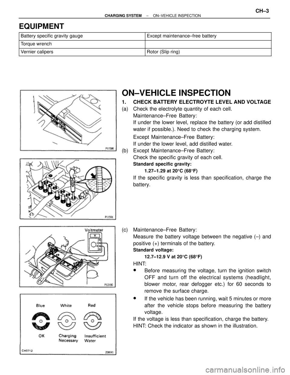
ON±VEHICLE INSPECTION
1. CHECK BATTERY ELECTROYTE LEVEL AND VOLTAGE
(a) Check the electrolyte quantity of each cell.
Maintenance±Free Battery:
If under the lower level, replace the battery (or add distilled
water if possible.). Need to check the charging system.
Except Maintenance±Free Battery:
If under the lower level, add distilled water.
(b) Except Maintenance±Free Battery:
Check the specific gravity of each cell.
Standard specific gravity:
1.27±1.29 at 205C (685F)
If the specific gravity is less than specification, charge the
battery.
(c) Maintenance±Free Battery:
Measure the battery voltage between the negative (±) and
positive (+) terminals of the battery.
Standard voltage:
12.7±12.9 V at 205C (685F)
HINT:
wBefore measuring the voltage, turn the ignition switch
OFF and turn off the electrical systems (headlight,
blower motor, rear defogger etc.) for 60 seconds to
remove the surface charge.
wIf the vehicle has been running, wait 5 minutes or more
after the vehicle stops before measuring the battery
voltage.
If the voltage is less than specification, charge the battery.
HINT: Check the indicator as shown in the illustration.
± CHARGING SYSTEMON±VEHICLE INSPECTIONCH±3
Page 1057 of 2543

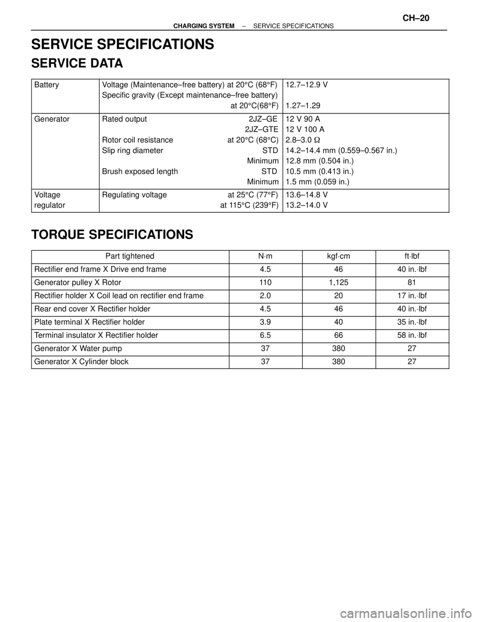
SERVICE SPECIFICATIONS
SERVICE DATA
������� �
������ �
������ �������
Battery���������������� �
��������������� �
��������������� ����������������
Voltage (Maintenance±free battery) at 205C (685F)
Specific gravity (Except maintenance±free battery)
at 205C(685F)��������������� �
�������������� �
�������������� ���������������
12.7±12.9 V
1.27±1.29
������� �
������ �
������ �
������ �
������ �
������ �������
Generator���������������� �
��������������� �
��������������� �
��������������� �
��������������� �
��������������� ����������������
Rated output 2JZ±GE
2JZ±GTE
Rotor coil resistance at 205C (685C)
Slip ring diameter STD
Minimum
Brush exposed length STD
Minimum��������������� �
�������������� �
�������������� �
�������������� �
�������������� �
�������������� ���������������
12 V 90 A
12 V 100 A
2.8±3.0 �
14.2±14.4 mm (0.559±0.567 in.)
12.8 mm (0.504 in.)
10.5 mm (0.413 in.)
1.5 mm (0.059 in.)
������� �
������ �������Voltage
regulator���������������� �
��������������� ����������������Regulating voltage at 255C (775F)
at 1155C (2395F)��������������� �
�������������� ���������������13.6±14.8 V
13.2±14.0 V
TORQUE SPECIFICATIONS
����������������� �����������������Part tightened������� �������NVm������� �������kgfVcm������� �������ftVlbf����������������� �����������������Rectifier end frame X Drive end frame������� �������4.5������� �������46������� �������40 in.Vlbf����������������� �
����������������
�����������������
Generator pulley X Rotor�������
������� �������11 0������� �
������ �������1,125������� �
������ �������81
����������������� �����������������Rectifier holder X Coil lead on rectifier end frame������� �������2.0������� �������20������� �������17 in.Vlbf
����������������� �����������������Rear end cover X Rectifier holder������� �������4.5������� �������46������� �������40 in.Vlbf
����������������� �����������������Plate terminal X Rectifier holder������� �������3.9������� �������40������� �������35 in.Vlbf
����������������� �����������������Terminal insulator X Rectifier holder������� �������6.5������� �������66������� �������58 in.Vlbf
����������������� �����������������Generator X Water pump������� �������37������� �������380������� �������27
����������������� �����������������Generator X Cylinder block������� �������37������� �������380������� �������27
± CHARGING SYSTEMSERVICE SPECIFICATIONSCH±20
Page 1097 of 2543
RADIATOR REMOVAL
Installation is in the reverse order of removal.
1. REMOVE ENGINE UNDER COVER
INSTALLATION HINT: Start the engine, and check for cool-
ant and A/T fluid leaks.
2. REMOVE BATTERY AND BATTERY TRAY
3. DRAIN ENGINE COOLANT
4. 2JZ±GTE:
REMOVE NO.2 AIR TUBE
5. REMOVE NO.2 FAN SHROUD
(a) Remove the 2 clips.
(b) Disconnect the claw of the No.2 fan shroud from the hook of
the No.1 fan shroud, and remove the No.2 fan shroud.
6. REMOVE AIR CLEANER DUCT
7. 2JZ±GTE:
REMOVE NO.5 AIR HOSE
8. REMOVE LH HEADLIGHT BEAM ANGLE GAUGE
Remove the screw and beam angle gauge.
9. DISCONNECT HOSES FROM RADIATOR
Disconnect these hoses from the radiator:
(1) Reservoir inlet hose
(2) Upper radiator hose
(3) Lower radiator hose
(4) A/T:
2 oil cooler hoses
Plug the hose ends.
INSTALLATION HINT: Check the A/T fluid level.
(See item 21 in Maintenance) EG±346
± ENGINECOOLING SYSTEM
Page 1234 of 2543
MAINTENANCE
GENERAL NOTES:
wThere are two separate maintenance schedules,
namely A and B, which apply to different driving
conditions. Find out how the vehicle is driven, select the
appropriate schedule and service the vehicle
accordingly.
wEvery service item in the periodic maintenance list must
be performed.
wNext to the columns of periods in the schedule,
reference pages have been added for easy access to
service data and procedures necessary for each
operation.
wThe service interval for scheduled maintenance is
determined by the odometer reading or time interval,
whichever comes first, shown in the schedule.
wMaintenance services after the last period should be
performed at the same interval as before unless
otherwise noted.
wSkipping even one item in the list can cause the engine
to run poorly and increase exhaust emissions.
MA±1
Page 1235 of 2543
MAINTENANCE SCHEDULE
SCHEDULE A
CONDITIONS:
wTowing a trailer, using a camper or car top carrier.
wRepeated short trips of less than 8 km (5 miles) with outside temperature remaining below freezing.
wExtensive idling and/or low speed driving for long distances, such as police, taxi or door±to ±door
delivery use.
wOperating on dusty, rough, muddy or salt spread roads.
Maintenance operation: A = Check and adjust if necessary.
R = Replace, change or lubricate.
I = Inspect and correct or replace if necessary.
MA±6
MA±9
MA±6
MA±7
MA±7
MA±7
MA±8
MA±8
MA±9
MA±9
MA±9
MA±6
MA±11
MA±11
MA±10
MA±12
MA±12
MA±13
MA±14, 15
MA±13
MA±16
See page
(item No.)System
ENGINE
FUEL
IGNITION
EVAP
BRAKES
CHASSIS
MA±2± MAINTENANCEMAINTENANCE SCHEDULE