Page 648 of 2543

SPEEDOMETER INSPECTION
ON±VEHICLE
Using a speedometer tester, inspect the speedometer for al-
lowable indication error and check the operation of the odom-
eter.
HINT: Tire wear and tire over or under inflation will increase
the indication error.
If error is excessive, replace the speedometer.
������������������ ������������������ USA (mph)������������������� ������������������� CANADA (km/h)
������������������ ������������������Standard indication Allowable range������������������� ������������������� Standard indication Allowable range������������������ �
����������������� ������������������20 18±24������������������� �
������������������ �������������������20 17±24
������������������ ������������������40 38±44������������������� �������������������40 38±46
������������������ ������������������60 56±66������������������� �������������������60 57.5±67
������������������ ������������������80 78±88������������������� �������������������80 77±88
������������������ ������������������100 98±110������������������� �������������������100 96±109������������������ �
����������������� ������������������120 118±132
������������������� �
������������������ �������������������120 115±130
������������������ ������������������������������������� �������������������140 134±151.5
������������������ ������������������������������������� �������������������160 153±173
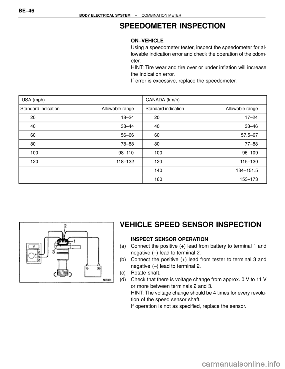
VEHICLE SPEED SENSOR INSPECTION
INSPECT SENSOR OPERATION
(a) Connect the positive (+) lead from battery to terminal 1 and
negative (±) lead to terminal 2.
(b) Connect the positive (+) lead from tester to terminal 3 and
negative (±) lead to terminal 2.
(c) Rotate shaft.
(d) Check that there is voltage change from approx. 0 V to 11 V
or more between terminals 2 and 3.
HINT: The voltage change should be 4 times for every revolu-
tion of the speed sensor shaft.
If operation is not as specified, replace the sensor. BE±46
± BODY ELECTRICAL SYSTEMCOMBINATION METER
Page 1633 of 2543
PRECAUTION
wCare must be taken to replace parts properly because they could affect the
performance of the steering system and result in a driving hazard.
wThe steering wheel pad has an SRS (Supplemental Restraint System) airbag built in,
so take all due precautions when handling it. For more details, see the RS section.
TROUBLESHOOTING
Use the table below to help you find the cause of the problem. The numbers indicate the priority of the likely
cause of the problem. Check each part in order. If necessary, repair or replace these parts.
SA±3SA±4SR±7SA±27SR±49SR±47SA±16
Tires (improperly inflated)Steering column (Binding)Suspension arm ball joints (Worn)Steering system joints (Worn)Drive belt (Loose)Fluid level (Low)Front wheel alignment (Incorrect)Electronic controlSolenoid valveSteering gear housingSliding yoke (Worn)Front wheel bearing (Worn)
Hard steering
Abnormal noise
Excessive play
Poor return
See page
Parts
Name
Trouble
SA±30
SR±2± STEERINGTROUBLESHOOTING
Page 1787 of 2543
SA±3SA±3SA±4SA±21
SA±85SA±32
SA±96SA±32
SA±96SA±26,29
SA±89,92SA±13
SA±35SA±20
SA±83SA±3
See Page
Parts
Name
Trouble
Wander / pulls
Bottoming
Sways / pitches
Front wheel shimmy
Abnormal tire wear
Cold tire inflation pressureTiresWheel alignmentSpringsStabilizer barShock absorberBall jointHub bearingsSteering linkageSteering gearSuspension partsOverloadWheel balance
TROUBLESHOOTING
Use the table below to help you find the cause of the problem. The numbers indicate the priority of the likely
cause of the problem. Check each part in order. If necessary, replace these parts. SA±2
± SUSPENSION AND AXLETROUBLESHOOTING
Page 1788 of 2543

GENERAL INSPECTION
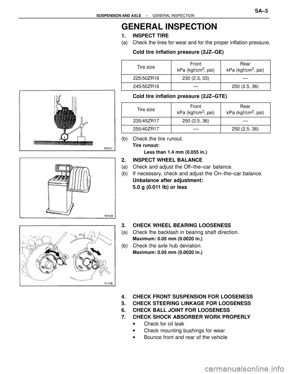
1. INSPECT TIRE
(a) Check the tires for wear and for the proper inflation pressure.
Cold tire inflation pressure (2JZ±GE)
�������� �
������� ��������Tire size�������� �
������� ��������
Front
kPa (kgf/cm2, psi)
�������� �
������� ��������
Rear
kPa (kgf/cm2, psi)
�������� ��������225/50ZR16�������� ��������230 (2.3, 33)�������� ��������±±
�������� ��������245/50ZR16�������� ��������±±�������� ��������250 (2.5, 36)
Cold tire inflation pressure (2JZ±GTE)
�������� �
������� ��������
Tire size�������� �
������� ��������
Front
kPa (kgf/cm2, psi)
�������� �
������� ��������
Rear
kPa (kgf/cm2, psi)
�������� ��������235/45ZR17�������� ��������250 (2.5, 36)�������� ��������±±
�������� ��������255/40ZR17�������� ��������±±�������� ��������250 (2.5, 36)
(b) Check the tire runout.
Tire runout:
Less than 1.4 mm (0.055 in.)
2. INSPECT WHEEL BALANCE
(a) Check and adjust the Off±the±car balance.
(b) If necessary, check and adjust the On±the±car balance.
Unbalance after adjustment:
5.0 g (0.011 lb) or less
3. CHECK WHEEL BEARING LOOSENESS
(a) Check the backlash in bearing shaft direction.
Maximum: 0.05 mm (0.0020 in.)
(b) Check the axle hub deviation.
Maximum: 0.05 mm (0.0020 in.)
4. CHECK FRONT SUSPENSION FOR LOOSENESS
5. CHECK STEERING LINKAGE FOR LOOSENESS
6. CHECK BALL JOINT FOR LOOSENESS
7. CHECK SHOCK ABSORBER WORK PROPERLY
wCheck for oil leak
wCheck mounting bushings for wear
wBounce front and rear of the vehicle
± SUSPENSION AND AXLEGENERAL INSPECTIONSA±3
Page 1884 of 2543
Cold tire
inflation
pressure
Vehicle height
Front wheel
alignment
Front axle hub
Front
suspension
Rear wheel
alignment
Rear axle hub
Rear
suspension
Rear
drive shaft
Toe±in
Camber
Caster
Steering axis
inclination
Wheel angle
(Max.)
Tie rod end left±right error
Bearing axial direction play
Upper ball joint turning torque
Axle hub flange runout
Bearing axial direction play
Stabilizer bar link ball joint turning torque
Lower ball joint turning torque
Axle hub flange runout
Stabilizer bar link ball joint turning torque
Lower ball joint turning torque
Lower ball joint turning torque
Toe±in
Camber
SERVICE SPECIFICATIONS
SERVICE DATA
± SUSPENSION AND AXLESERVICE SPECIFICATIONSSA±99