Page 792 of 2543

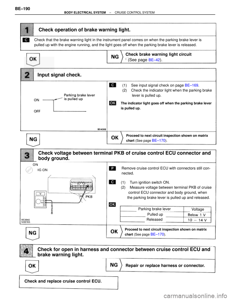
(See page BE±42).
BE±169.
Proceed to next circuit inspection shown on matrix
chart (See page
BE±170).
(1) See input signal check on page BE±169.
(2) Check the indicator light when the parking brake
lever is pulled up.
Check operation of brake warning light.
Check voltage between terminal PKB of cruise control ECU connector and
body ground.
(1) Turn ignition switch ON.
(2) Measure voltage between terminal PKB of cruise
control ECU connector and body ground, when
the parking brake lever is pulled up and released.
Remove cruise control ECU with connectors still con-
nected.
Input signal check.
The indicator light goes off when the parking brake lever
is pulled up.
Check that the brake warning light in the instrument panel comes on when the parking brake lever is
pulled up with the engine running, and the light goes off when the parking brake lever is released.
Check brake warning light circuit
Parking brake lever
Proceed to next circuit inspection shown on matrix
chart (See page
BE±170).
Voltage
Pulled up
Released
Check for open in harness and connector between cruise control ECU and
brake warning light.
Repair or replace harness or connector.
Check and replace cruise control ECU. BE±190
± BODY ELECTRICAL SYSTEMCRUISE CONTROL SYSTEM
Page 837 of 2543

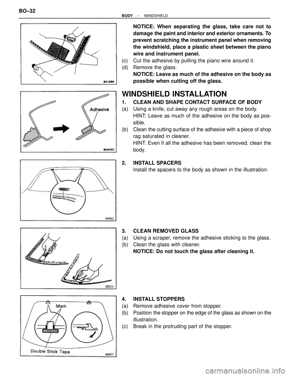
NOTICE: When separating the glass, take care not to
damage the paint and interior and exterior ornaments. To
prevent scratching the instrument panel when removing
the windshield, place a plastic sheet between the piano
wire and instrument panel.
(c) Cut the adhesive by pulling the piano wire around it.
(d) Remove the glass.
NOTICE: Leave as much of the adhesive on the body as
possible when cutting off the glass.
WINDSHIELD INSTALLATION
1. CLEAN AND SHAPE CONTACT SURFACE OF BODY
(a) Using a knife, cut away any rough areas on the body.
HINT: Leave as much of the adhesive on the body as pos-
sible.
(b) Clean the cutting surface of the adhesive with a piece of shop
rag saturated in cleaner.
HINT: Even if all the adhesive has been removed, clean the
body.
2. INSTALL SPACERS
Install the spacers to the body as shown in the illustration.
3. CLEAN REMOVED GLASS
(a) Using a scraper, remove the adhesive sticking to the glass.
(b) Clean the glass with cleaner.
NOTICE: Do not touch the glass after cleaning it.
4. INSTALL STOPPERS
(a) Remove adhesive cover from stopper.
(b) Position the stopper on the edge of the glass as shown on the
illustration.
(c) Break in the protruding part of the stopper. BO±32
± BODYWINDSHIELD
Page 849 of 2543
INSTRUMENT PANEL
COMPONENTS
BO±44± BODYINSTRUMENT PANEL
Page 850 of 2543
COMPONENTS (Cont'd)
± BODYINSTRUMENT PANELBO±45
Page 851 of 2543
COMPONENTS (Cont'd)
BO±46± BODYINSTRUMENT PANEL
Page 852 of 2543
HINT: Screws in the illustration on the previous pages are in-
dicated using the code below for removal and installation of
instrument panel.
mm(in.)
ShapeShapeShapeSizeSizeSize
± BODYINSTRUMENT PANELBO±47
Page 853 of 2543
INSTRUMENT PANEL REMOVAL
1. REMOVE STEERING WHEEL
(See page SR±14)
CAUTION:
wWhen storing the wheel pad, keep the upper surface of
the pad facing upward.
wNever disassemble the steering wheel pad.
2. REMOVE THESE PARTS:
HINT: Tape a screwdriver tip before use.
(a) Front pillar garnishes
(b) Assist grip
(c) Foot rest
(d) Front door scuff inside plates
(e) Steering column cover
(f) Console upper panel
(g) Parking brake hole cover
(h) Console box
(i) Finish panel
(j) Finish lower LH panel
(k) Cluster finish panel BO±48
± BODYINSTRUMENT PANEL
Page 854 of 2543
(l) Cluster finish panel center
(m) Cluster finish panel LH
(n) Cluster finish panel RH
(o) Combination meter
(p) Heater to register No.2 duct
(q) Combination switch
(r) Audio receiver assembly
(s) Computer cover
3. REMOVE INSTRUMENT PANEL BOX
HINT: Tape a screwdriver tip before use.
(a) Remove the glove compartment door finish plate inside the
instrument panel box.
NOTICE: When handling the airbag connector, take care
not to damage the airbag wire harness.
(b) Pull up and disconnect the airbag connector.
(c) Remove the instrument panel box.
4. REMOVE THESE PARTS
(a) Finish panel mounting No.3 and 4 bracket
(b) Heater to register No.4 duct
(c) Finish panel mounting No.2 bracket
± BODYINSTRUMENT PANELBO±49