Page 47 of 2543
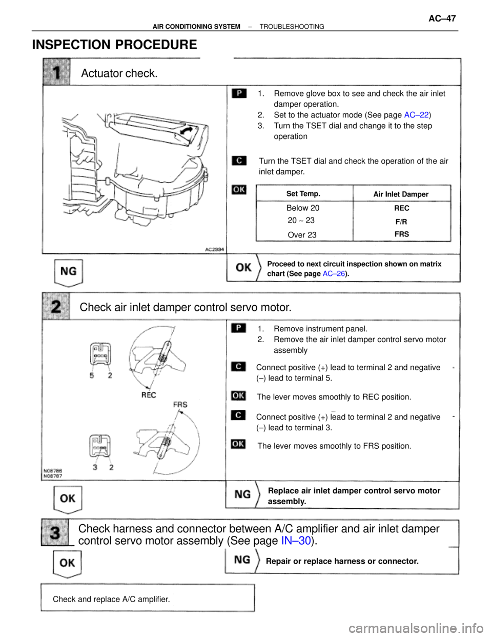
(See page AC±26).
(See page IN±30).
AC±22).
Actuator check.
Check air inlet damper control servo motor.
Check and replace A/C amplifier.
Repair or replace harness or connector.
Replace air inlet damper control servo motor
assembly.
Check harness and connector between A/C amplifier and air inlet damper
control servo motor assembly (See page IN±30).
Proceed to next circuit inspection shown on matrix
chart (See page AC±26).
Turn the TSET dial and check the operation of the air
inlet damper.
The lever moves smoothly to FRS position.
The lever moves smoothly to REC position.
Set Temp.Air Inlet Damper
Below 20
Over 23
20 ~ 23
REC
F/R
FRS
1. Remove glove box to see and check the air inlet
damper operation.
2. Set to the actuator mode (See page AC±22)
3. Turn the TSET dial and change it to the step
operation
1. Remove instrument panel.
2. Remove the air inlet damper control servo motor
assembly
Connect positive (+) lead to terminal 2 and negative
(±) lead to terminal 3.
Connect positive (+) lead to terminal 2 and negative
(±) lead to terminal 5.
INSPECTION PROCEDURE
± AIR CONDITIONING SYSTEMTROUBLESHOOTINGAC±47
Page 95 of 2543
EVAPORATOR
EVAPORATOR REMOVAL
1. DISCHARGE REFRIGERANT IN REFRIGERATION
SYSTEM
INSTALLATION HINT: Evacuate air from refrigeration sys-
tem.
Charge system with refrigerant and inspect for leakage of re-
frigerant.
2. REMOVE ABS ACTUATOR (w/ABS)
(See page BR±44)
3. REMOVE LIQUID TUBE AND SUCTION TUBE FROM A/C
UNIT
Torque: 10 NVm (100 kgfVcm, 7 ftVlbf)
INSTALLATION HINT: Lubricate the new O±rings with com-
pressor oil and install the tubes.
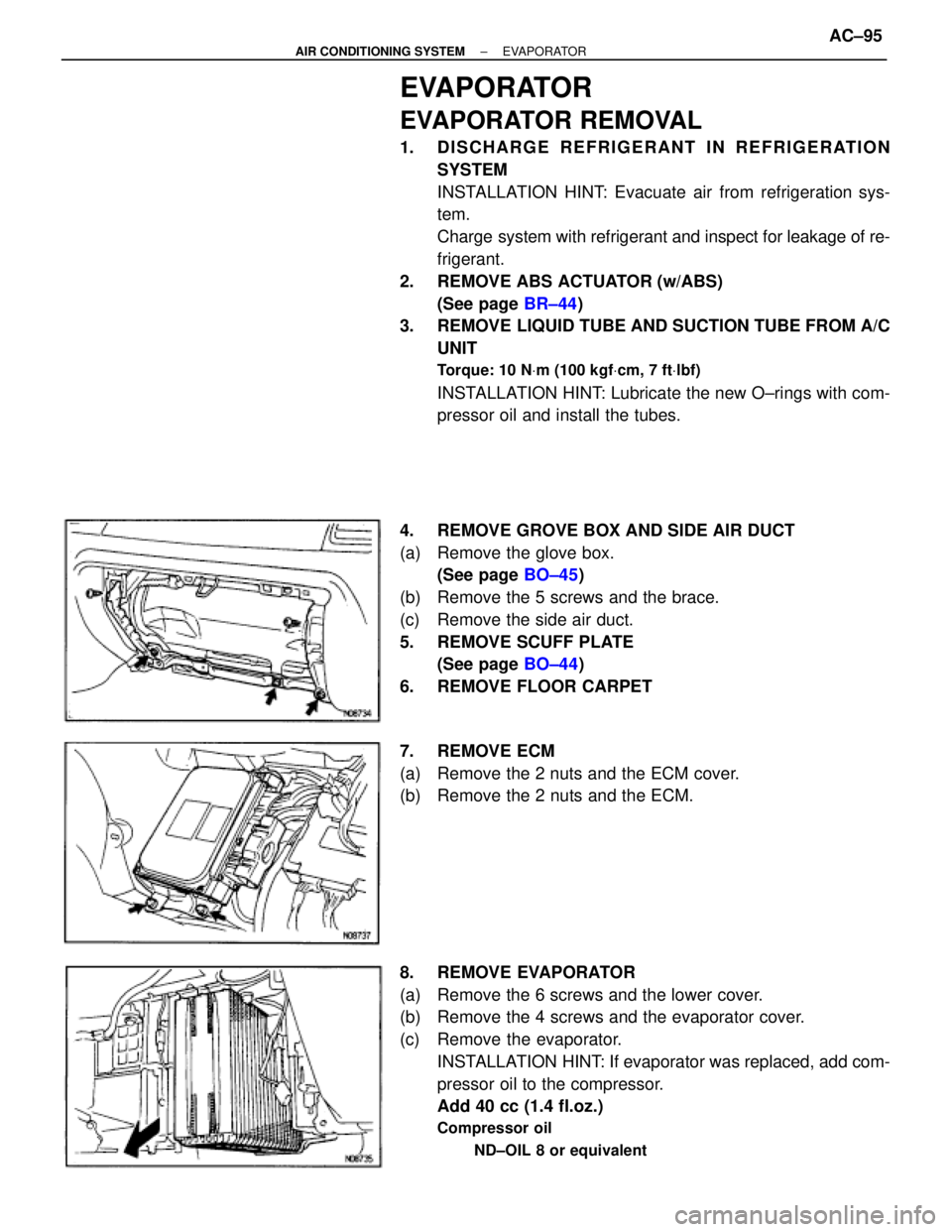
4. REMOVE GROVE BOX AND SIDE AIR DUCT
(a) Remove the glove box.
(See page BO±45)
(b) Remove the 5 screws and the brace.
(c) Remove the side air duct.
5. REMOVE SCUFF PLATE
(See page BO±44)
6. REMOVE FLOOR CARPET
7. REMOVE ECM
(a) Remove the 2 nuts and the ECM cover.
(b) Remove the 2 nuts and the ECM.
8. REMOVE EVAPORATOR
(a) Remove the 6 screws and the lower cover.
(b) Remove the 4 screws and the evaporator cover.
(c) Remove the evaporator.
INSTALLATION HINT: If evaporator was replaced, add com-
pressor oil to the compressor.
Add 40 cc (1.4 fl.oz.)
Compressor oil
ND±OIL 8 or equivalent
± AIR CONDITIONING SYSTEMEVAPORATORAC±95
Page 99 of 2543
BLOWER MOTOR
BLOWER MOTOR REMOVAL
1. REMOVE GLOVE BOX AND SIDE AIR DUCT
(a) Remove the glove box.
(See page BO±45)
(b) Remove the 5 bolts and the brace.
(c) Remove the side air duct.
2. REMOVE SCUFF PLATE
(See page BO±44)
3. REMOVE FLOOR CARPET
4. REMOVE ECM COVER
Remove the 2 nuts and the ECM cover.
5. REMOVE BLOWER MOTOR
(a) Disconnect the connector.
(b) Remove the 3 screws and the blower motor.
BLOWER MOTOR INSPECTION
(See page AC±61)
BLOWER MOTOR INSTALLATION
Installation is in the reverse order of removal.
± AIR CONDITIONING SYSTEMBLOWER MOTORAC±99
Page 854 of 2543
(l) Cluster finish panel center
(m) Cluster finish panel LH
(n) Cluster finish panel RH
(o) Combination meter
(p) Heater to register No.2 duct
(q) Combination switch
(r) Audio receiver assembly
(s) Computer cover
3. REMOVE INSTRUMENT PANEL BOX
HINT: Tape a screwdriver tip before use.
(a) Remove the glove compartment door finish plate inside the
instrument panel box.
NOTICE: When handling the airbag connector, take care
not to damage the airbag wire harness.
(b) Pull up and disconnect the airbag connector.
(c) Remove the instrument panel box.
4. REMOVE THESE PARTS
(a) Finish panel mounting No.3 and 4 bracket
(b) Heater to register No.4 duct
(c) Finish panel mounting No.2 bracket
± BODYINSTRUMENT PANELBO±49
Page 1706 of 2543
FRONT PASSENGER AIRBAG
ASSEMBLY REMOVAL AND
INSTALLATION
NOTICE:
wIf the wiring connector of the SRS is disconnected with
the ignition switch at ON or ACC, diagnostic trouble
codes will be recorded.
wNever use airbag parts from another vehicle. When
replacing parts, replace with new parts.
1. DISCONNECT AIRBAG CONNECTOR
(a) Remove negative (±) terminal cable from the battery, and
wait at least 90 seconds.
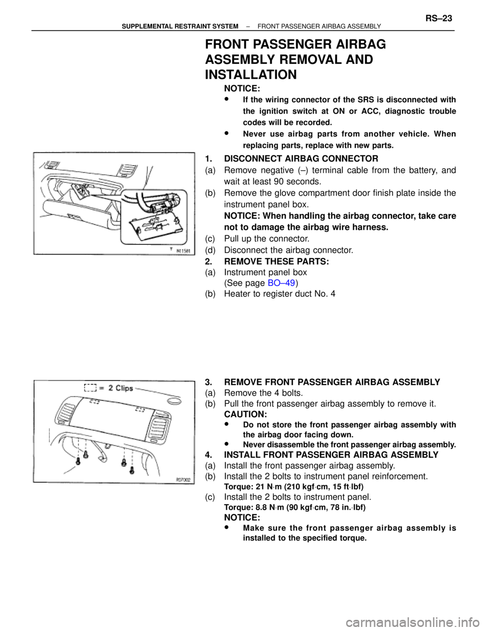
(b) Remove the glove compartment door finish plate inside the
instrument panel box.
NOTICE: When handling the airbag connector, take care
not to damage the airbag wire harness.
(c) Pull up the connector.
(d) Disconnect the airbag connector.
2. REMOVE THESE PARTS:
(a) Instrument panel box
(See page BO±49)
(b) Heater to register duct No. 4
3. REMOVE FRONT PASSENGER AIRBAG ASSEMBLY
(a) Remove the 4 bolts.
(b) Pull the front passenger airbag assembly to remove it.
CAUTION:
wDo not store the front passenger airbag assembly with
the airbag door facing down.
wNever disassemble the front passenger airbag assembly.
4. INSTALL FRONT PASSENGER AIRBAG ASSEMBLY
(a) Install the front passenger airbag assembly.
(b) Install the 2 bolts to instrument panel reinforcement.
Torque: 21 NVm (210 kgfVcm, 15 ftVlbf)
(c) Install the 2 bolts to instrument panel.
Torque: 8.8 NVm (90 kgfVcm, 78 in.Vlbf)
NOTICE:
wMake sure the front passenger airbag assembly is
installed to the specified torque.
± SUPPLEMENTAL RESTRAINT SYSTEMFRONT PASSENGER AIRBAG ASSEMBLYRS±23
Page 1707 of 2543
wIf the front passenger airbag assembly has been
dropped, or there are cracks, dents or other defects in the
case or connector, replace the front passenger airbag
assembly with a new one.
wAdhesive has been applied to the 2 instrument panel
bolts. When the front passenger airbag assembly is
removed, always replace the bolts with new ones.
wWhen installing the front passenger airbag assembly,
take care that the wirings do not interfere with other parts
and are not pinched between other parts.
5. INSTALL THESE PARTS:
(a) Heater to register duct No. 4
(b) Instrument panel box
(See page BO±49)
NOTICE: When installing the instrument panel box, care-
fully pull out the airbag wire harness from the glove
compartment upper hole.
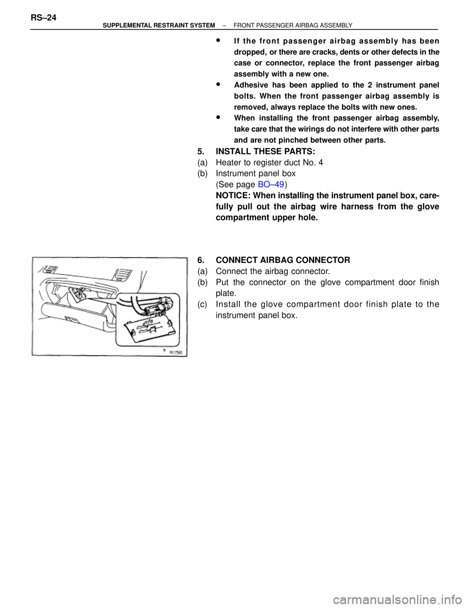
6. CONNECT AIRBAG CONNECTOR
(a) Connect the airbag connector.
(b) Put the connector on the glove compartment door finish
plate.
(c) Install the glove compartment door finish plate to the
instrument panel box. RS±24
± SUPPLEMENTAL RESTRAINT SYSTEMFRONT PASSENGER AIRBAG ASSEMBLY
Page 1709 of 2543
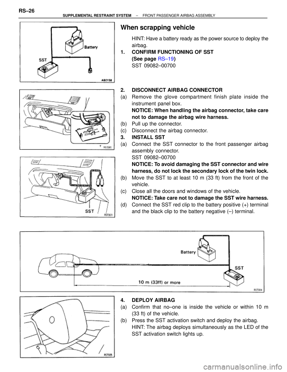
When scrapping vehicle
HINT: Have a battery ready as the power source to deploy the
airbag.
1. CONFIRM FUNCTIONING OF SST
(See page RS±19)
SST 09082±00700
2. DISCONNECT AIRBAG CONNECTOR
(a) Remove the glove compartment finish plate inside the
instrument panel box.
NOTICE: When handling the airbag connector, take care
not to damage the airbag wire harness.
(b) Pull up the connector.
(c) Disconnect the airbag connector.
3. INSTALL SST
(a) Connect the SST connector to the front passenger airbag
assembly connector.
SST 09082±00700
NOTICE: To avoid damaging the SST connector and wire
harness, do not lock the secondary lock of the twin lock.
(b) Move the SST to at least 10 m (33 ft) from the front of the
vehicle.
(c) Close all the doors and windows of the vehicle.
NOTICE: Take care not to damage the SST wire harness.
(d) Connect the SST red clip to the battery positive (+) terminal
and the black clip to the battery negative (±) terminal.
4. DEPLOY AIRBAG
(a) Confirm that no±one is inside the vehicle or within 10 m
(33 ft) of the vehicle.
(b) Press the SST activation switch and deploy the airbag.
HINT: The airbag deploys simultaneously as the LED of the
SST activation switch lights up. RS±26
± SUPPLEMENTAL RESTRAINT SYSTEMFRONT PASSENGER AIRBAG ASSEMBLY