Page 3 of 2543

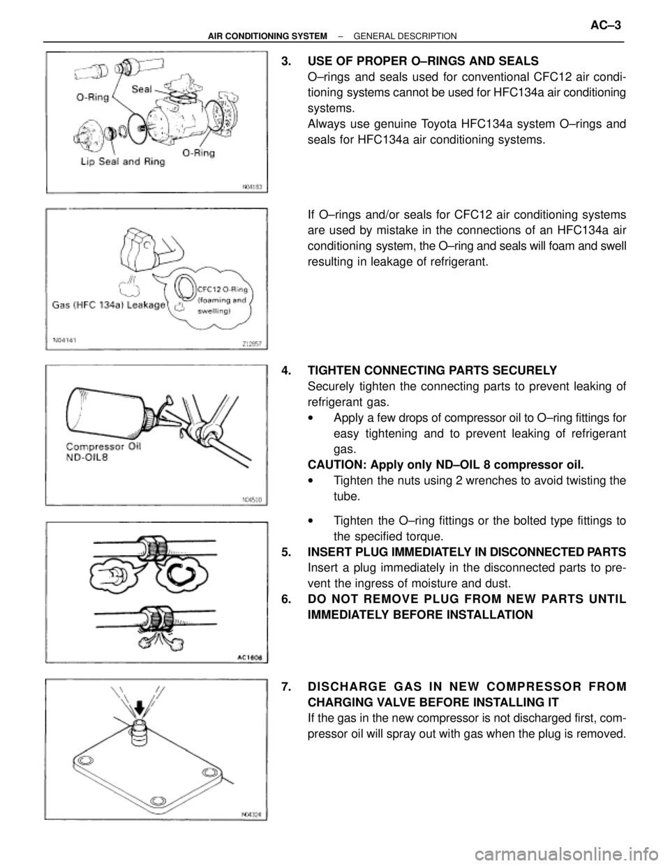
3. USE OF PROPER O±RINGS AND SEALS
O±rings and seals used for conventional CFC12 air condi-
tioning systems cannot be used for HFC134a air conditioning
systems.
Always use genuine Toyota HFC134a system O±rings and
seals for HFC134a air conditioning systems.
If O±rings and/or seals for CFC12 air conditioning systems
are used by mistake in the connections of an HFC134a air
conditioning system, the O±ring and seals will foam and swell
resulting in leakage of refrigerant.
4. TIGHTEN CONNECTING PARTS SECURELY
Securely tighten the connecting parts to prevent leaking of
refrigerant gas.
wApply a few drops of compressor oil to O±ring fittings for
easy tightening and to prevent leaking of refrigerant
gas.
CAUTION: Apply only ND±OIL 8 compressor oil.
wTighten the nuts using 2 wrenches to avoid twisting the
tube.
wTighten the O±ring fittings or the bolted type fittings to
the specified torque.
5. INSERT PLUG IMMEDIATELY IN DISCONNECTED PARTS
Insert a plug immediately in the disconnected parts to pre-
vent the ingress of moisture and dust.
6. DO NOT REMOVE PLUG FROM NEW PARTS UNTIL
IMMEDIATELY BEFORE INSTALLATION
7. DISCHARGE GAS IN NEW COMPRESSOR FROM
CHARGING VALVE BEFORE INSTALLING IT
If the gas in the new compressor is not discharged first, com-
pressor oil will spray out with gas when the plug is removed.
± AIR CONDITIONING SYSTEMGENERAL DESCRIPTIONAC±3
Page 5 of 2543

HANDLING PRECAUTIONS FOR
REFRIGERANT
1. DO NOT HANDLE REFRIGERANT IN AN ENCLOSED
AREA OR NEAR AN OPEN FLAME
2. ALWAYS WEAR EYE PROTECTION
3. BE CAREFUL THAT LIQUID REFRIGERANT DOES NOT
GET IN YOUR EYES OR ON YOUR SKIN
If liquid refrigerant gets in your eyes or on your skin:
(a) Wash the area with lots of cool water.
CAUTION: Do not rub your eyes or skin.
(b) Apply clean petroleum jelly to the skin.
(c) Go immediately to a physician or hospital for professional
treatment.
HANDLING PRECAUTIONS FOR
REFRIGERANT CONTAINER
1. NEVER HEAT CONTAINER OR EXPOSE IT TO NAKED
FLAME
2. BE CAREFUL NOT TO DROP CONTAINER AND NOT TO
APPLY PHYSICAL SHOCKS TO IT
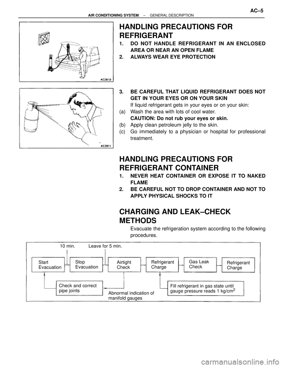
CHARGING AND LEAK±CHECK
METHODS
Evacuate the refrigeration system according to the following
procedures.
Start
EvacuationStop
EvacuationAirtight
CheckRefrigerant
ChargeRefrigerant
ChargeGas Leak
Check
Check and correct
pipe jointsFill refrigerant in gas state until
gauge pressure reads 1 kg/cm2Abnormal indication of
manifold gauges
10 min.Leave for 5 min.
± AIR CONDITIONING SYSTEMGENERAL DESCRIPTIONAC±5
Page 6 of 2543

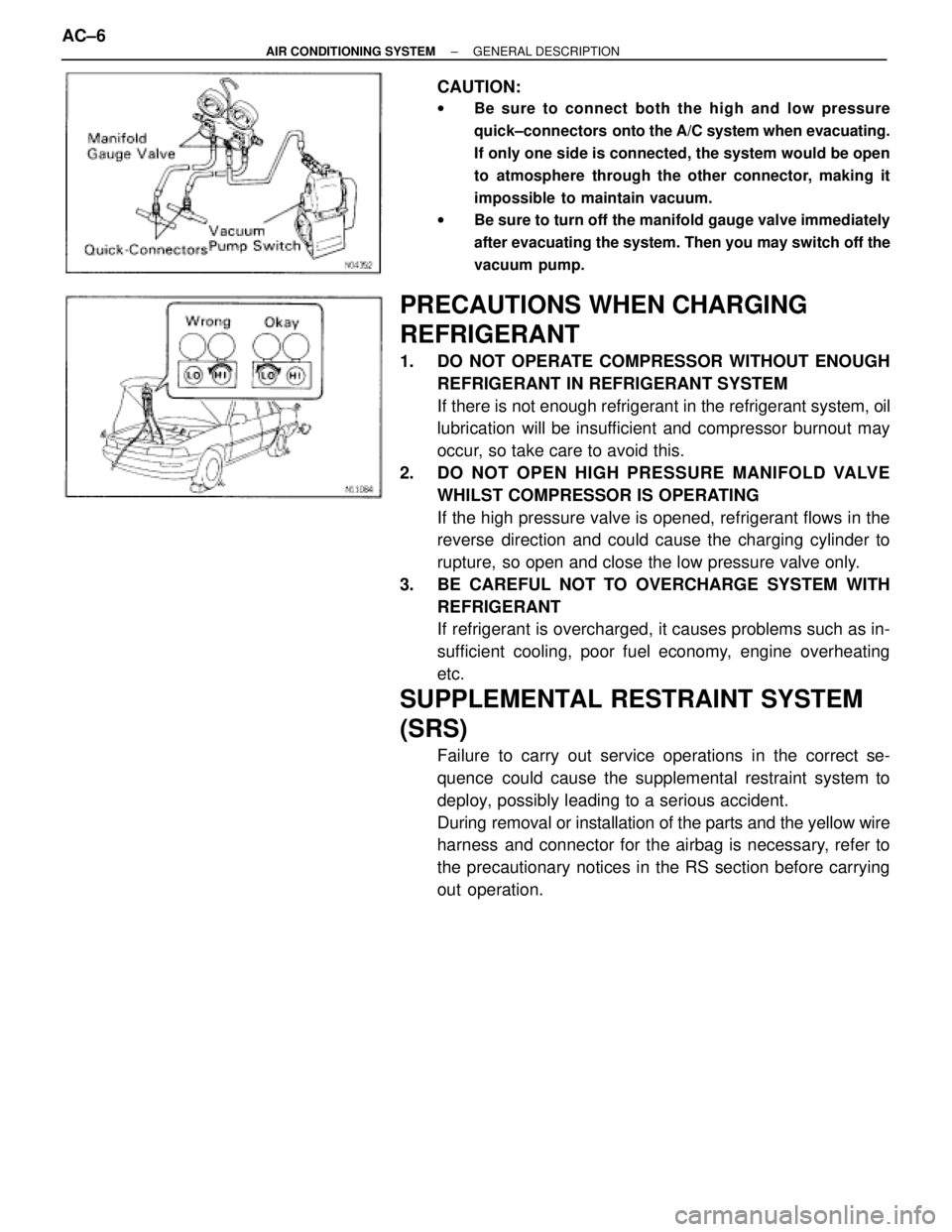
CAUTION:
wBe sure to connect both the high and low pressure
quick±connectors onto the A/C system when evacuating.
If only one side is connected, the system would be open
to atmosphere through the other connector, making it
impossible to maintain vacuum.
wBe sure to turn off the manifold gauge valve immediately
after evacuating the system. Then you may switch off the
vacuum pump.
PRECAUTIONS WHEN CHARGING
REFRIGERANT
1. DO NOT OPERATE COMPRESSOR WITHOUT ENOUGH
REFRIGERANT IN REFRIGERANT SYSTEM
If there is not enough refrigerant in the refrigerant system, oil
lubrication will be insufficient and compressor burnout may
occur, so take care to avoid this.
2. DO NOT OPEN HIGH PRESSURE MANIFOLD VALVE
WHILST COMPRESSOR IS OPERATING
If the high pressure valve is opened, refrigerant flows in the
reverse direction and could cause the charging cylinder to
rupture, so open and close the low pressure valve only.
3. BE CAREFUL NOT TO OVERCHARGE SYSTEM WITH
REFRIGERANT
If refrigerant is overcharged, it causes problems such as in-
sufficient cooling, poor fuel economy, engine overheating
etc.
SUPPLEMENTAL RESTRAINT SYSTEM
(SRS)
Failure to carry out service operations in the correct se-
quence could cause the supplemental restraint system to
deploy, possibly leading to a serious accident.
During removal or installation of the parts and the yellow wire
harness and connector for the airbag is necessary, refer to
the precautionary notices in the RS section before carrying
out operation. AC±6
± AIR CONDITIONING SYSTEMGENERAL DESCRIPTION
Page 9 of 2543
PREPARATION
SST (SPECIAL SERVICE TOOLS)
Air Conditioner Service Tool Set
Refrigerant Drain Service Valve
T±Joint
Quick Coupler
Quick Coupler
Refrigerant Charging Gauge
Refrigerant Charging Hose
Refrigerant Charging Hose
Refrigerant Charging Hose
Magnetic Clutch Remover
Magnetic Clutch Stopper
Snap Ring Pliers
Gas Leak Detector Assembly
Discharge (diam. 16 mm)
Suction (diam. 16 mm)
Suction (Blue)
Discharge (Red)
Utility (Green)
± AIR CONDITIONING SYSTEMPREPARATIONAC±9
Page 11 of 2543
USE OF MANIFOLD GAUGE SET
MANIFOLD GAUGE SET INSTALLATION
1. CONNECT CHARGING HOSES TO MANIFOLD GAUGE
SET
Tighten the nuts by hand.
CAUTION: Do not connect the wrong hoses.
2. CONNECT QUICK CONNECTORS TO CHARGING HOSES
Tighten the nuts by hand.
3. CLOSE BOTH HAND VALVES OF MANIFOLD GAUGE
SET
4. REMOVE CAPS FROM SERVICE VALVES ON
REFRIGERANT LINE
5. CONNECT QUICK CONNECTORS TO SERVICE VALVES
HINT: Push the quick connector onto the service valve, then
slide the sleeve of the quick connector downward to lock it.
MANIFOLD GAUGE SET REMOVAL
1. CLOSE BOTH HAND VALVES OF MANIFOLD GAUGE
SET
2. DISCONNECT QUICK CONNECTORS FROM SERVICE
VALVES ON REFRIGERANT LINE
HINT: Slide the sleeve of the quick connector upward to un-
lock the connector and remove it from the service valve.
3. INSTALL CAPS TO SERVICE VALVES ON REFRIGERANT
LINE
± AIR CONDITIONING SYSTEMUSE OF MANIFOLD GAUGE SETAC±11
Page 962 of 2543
Check battery positive voltage.
Remove ABS (& TRAC) ECU with connectors still
connected.
1. Turn ignition switch ON.
2. Measure voltage between terminals IG1 and
GND of ABS (& TRAC) ECU connector.
Voltage: 10 Ð 14 V
Check and repair the charging system.
Voltage: 10 Ð 14 V
Check voltage between terminals IG1 and GND of ABS (& TRAC) ECU
connector.
Check and replace ABS (& TRAC) ECU.
INSPECTION PROCEDURE.
± BRAKE SYSTEMANTI±LOCK BRAKE SYSTEM (ABS)BR±93
Page 1012 of 2543
INSPECTION PROCEDURE
Check battery positive voltage.
Voltage: 10 ± 14 V
Check and repair the charging system.
Remove TRAC ECU with connectors still
connected.
Turn ignition switch ON.
Measure voltage between terminals IG1 and
GND of TRAC ECU connector.
Voltage: 10 ± 14 V
Check voltage between terminals IG1 and GND of TRAC ECU connector.
Check and replace TRAC ECU.
Measure resistance between terminal GND of
TRAC ECU connector and body ground.
Resistance: 1� or less
Check continuity between terminal GND of TRAC ECU connector and
body ground.
Repair or replace harness or connector.
± BRAKE SYSTEMTRACTION CONTROL SYSTEM (TRAC)BR±143
Page 1037 of 2543