Page 17 of 2543
Warning for A/C compressor lock
If compressor lock occurs during air conditioning operation,
the [A/C] switch indicator on the air conditioning control as-
sembly starts blinking.
When this occurs, check for compressor lock using panel
diagnosis check then proceed to inspect the circuit or the
component.
Compressor lock sensor circuit " page AC±38
LIST OF OPERATION METHODS
By operating each of the air conditioning control switches as shown in the diagram below, it is possible to
enter the diagnosis check mode.
Indicator Check
Diagnostic
Sensor Check
(continuous operation)
Diagnostic
Sensor Check
(stepped operation)
Cancel check mode and can start
conditioning control
Actuator Check
(continuous
operation)
Turn ignition switch ON with AUTO and
switches held down.
If both Auto switch and switch are
not pressed at the same time.
: Indicates a switch operation
± AIR CONDITIONING SYSTEMTROUBLESHOOTINGAC±17
Page 41 of 2543

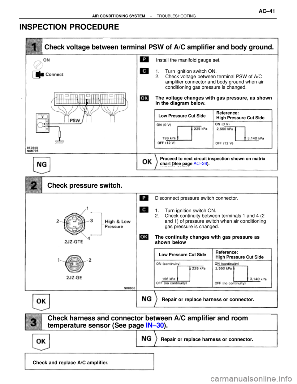
Check voltage between terminal PSW of A/C amplifier and body ground.
Check pressure switch.
Repair or replace harness or connector.
Check and replace A/C amplifier.
Repair or replace harness or connector.
Check harness and connector between A/C amplifier and room
temperature sensor (See page IN±30).
Proceed to next circuit inspection shown on matrix
chart (See page AC±26).
Install the manifold gauge set.
The voltage changes with gas pressure, as shown
in the diagram below.
1. Turn ignition switch ON.
2. Check voltage between terminal PSW of A/C
amplifier connector and body ground when air
conditioning gas pressure is changed.
Disconnect pressure switch connector.
1. Turn ignition switch ON.
2. Check continuity between terminals 1 and 4 (2
and 1) of pressure switch when air conditioning
gas pressure is changed.
The continuity changes with gas pressure as
shown below
Low Pressure Cut Side
Low Pressure Cut SideReference:
High Pressure Cut Side
Reference:
High Pressure Cut Side
INSPECTION PROCEDURE
± AIR CONDITIONING SYSTEMTROUBLESHOOTINGAC±41
Page 53 of 2543
INSPECTION PROCEDURE
Remove the A/C amplifier with connector still con-
ected.
Measure voltage between terminal + B of air condi-
tioner control assembly connector and body ground.
Voltage: Battery positive voltage
Proceed to next circuit inspection shown on matrix
chart (See page AC±26).
Remove ECU±B fuse from J/B No. 1.
Check continuity of ECU±B fuse.
Continuity
Check ECU±B fuse.
Check for short in all the harness and compo-
nents to the ECU±B fuse (See attached wiring
diagram).
Check voltage between terminal +B of A/C amplifier connector and
body ground.
Check and repair harness and connector between
A/C amplifier and battery.
± AIR CONDITIONING SYSTEMTROUBLESHOOTINGAC±53
Page 55 of 2543
Check continuity between terminal GND of A/C amplifier and body
ground.
Measure resistance between terminal GND of A/C
amplifier and body ground.
Remove HTR fuse from J/B No. 1.
Check continuity of HTR fuse.
Continuity
Check for short in all the harness and compo-
nents to the HTR fuse (See attached wiring
diagram).
Check and repair harness and connector between
A/C amplifier and battery.
Check HTR fuse.
Repair or replace harness or connector.
Resistance: O �� �continuity)
± AIR CONDITIONING SYSTEMTROUBLESHOOTINGAC±55
Page 57 of 2543
INSPECTION PROCEDURE
Check voltage between terminal ACC of A/C amplifier connector and
body ground.
Remove the A/C amplifier with connector still connected
Voltage: Battery positive voltage
1. Turn ignition switch To ACC.
2. Measure voltage between terminals ACC of A/C
amplifier connector and body ground.
Remove CIG fuse from J/B No. 1.
Check continuity of CIG fuse.
Continuity
Proceed to next circuit inspection shown on matrix
chart (See page AC±26).
Check CIG fuse.
Check for short in all the harness and compo-
nents to the CIG fuse (See attached wiring
diagram).
Check and repair harness and connector between
A/C amplifier and battery.
± AIR CONDITIONING SYSTEMTROUBLESHOOTINGAC±57
Page 59 of 2543

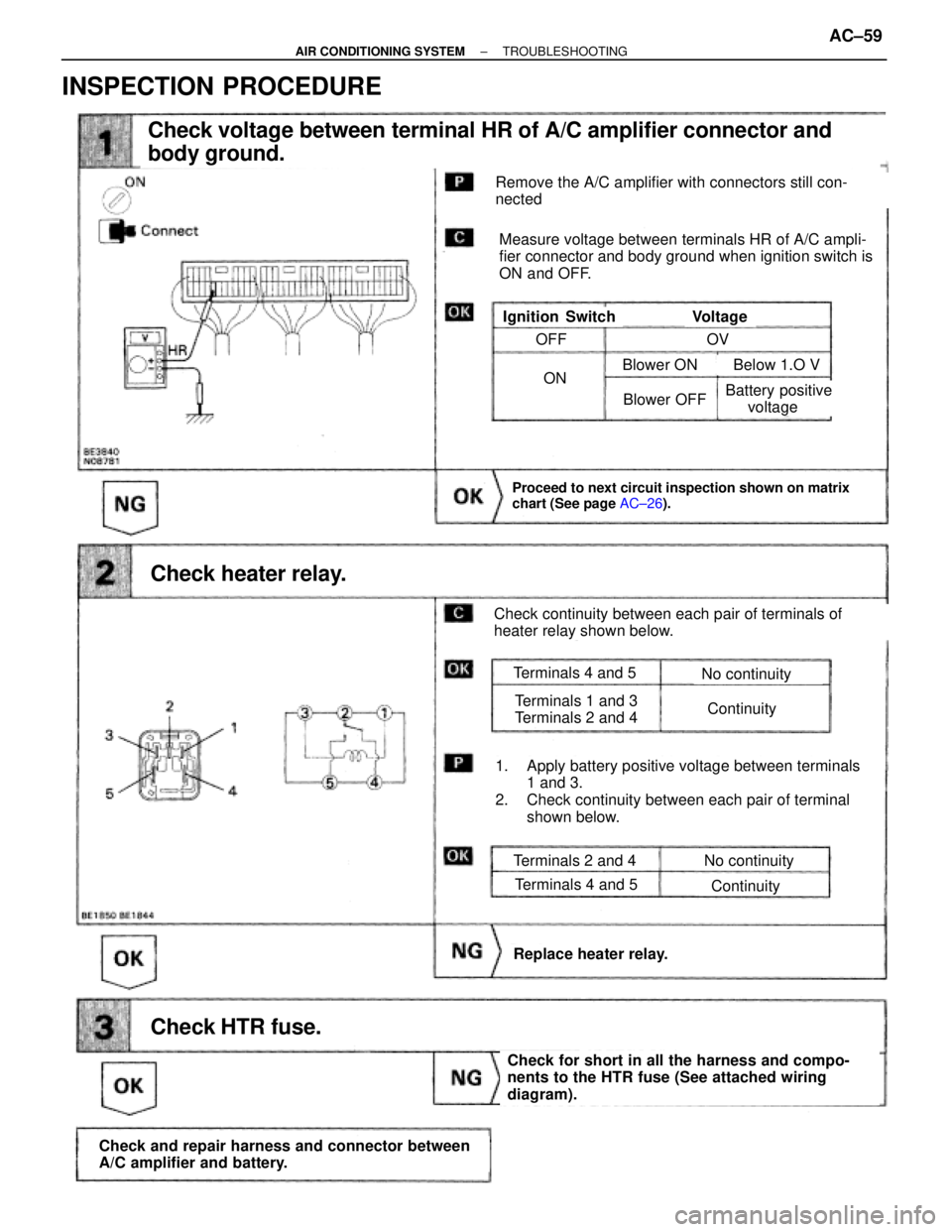
Check voltage between terminal HR of A/C amplifier connector and
body ground.
Check heater relay.
Proceed to next circuit inspection shown on matrix
chart (See page AC±26).
Check HTR fuse.
Check and repair harness and connector between
A/C amplifier and battery.
Check for short in all the harness and compo-
nents to the HTR fuse (See attached wiring
diagram).
Replace heater relay.
Remove the A/C amplifier with connectors still con-
nected
Measure voltage between terminals HR of A/C ampli-
fier connector and body ground when ignition switch is
ON and OFF.
VoltageIgnition Switch
Check continuity between each pair of terminals of
heater relay shown below.
1. Apply battery positive voltage between terminals
1 and 3.
2. Check continuity between each pair of terminal
shown below.
Terminals 2 and 4
Terminals 4 and 5
No continuity
Continuity
Terminals 4 and 5
Terminals 1 and 3
Terminals 2 and 4
No continuity
Continuity
OFF
ON
OV
Blower OFF
Blower ON Below 1.O V
Battery positive
voltage
INSPECTION PROCEDURE
± AIR CONDITIONING SYSTEMTROUBLESHOOTINGAC±59
Page 395 of 2543
SYSTEM DIAGRAM
± AT340E (2JZ±GE) AUTOMATIC TRANSMISSIONOPERATIONAT1±9
Page 414 of 2543
SHIFT LOCK SYSTEM
COMPONENT PARTS LOCATION
WIRING DIAGRAM
AT1±28± AT340E (2JZ±GE) AUTOMATIC TRANSMISSIONSHIFT LOCK SYSTEM