Page 1331 of 2543

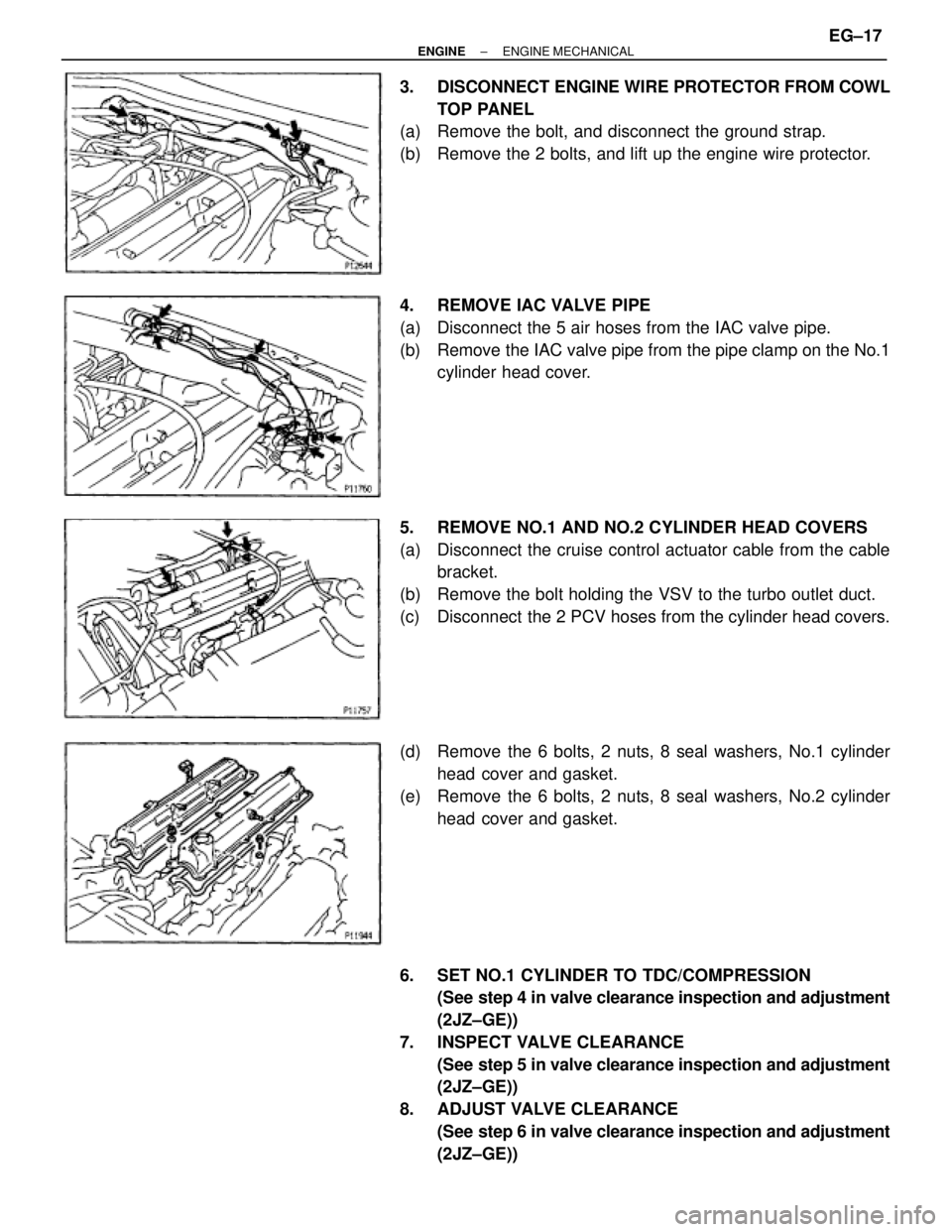
3. DISCONNECT ENGINE WIRE PROTECTOR FROM COWL
TOP PANEL
(a) Remove the bolt, and disconnect the ground strap.
(b) Remove the 2 bolts, and lift up the engine wire protector.
4. REMOVE IAC VALVE PIPE
(a) Disconnect the 5 air hoses from the IAC valve pipe.
(b) Remove the IAC valve pipe from the pipe clamp on the No.1
cylinder head cover.
5. REMOVE NO.1 AND NO.2 CYLINDER HEAD COVERS
(a) Disconnect the cruise control actuator cable from the cable
bracket.
(b) Remove the bolt holding the VSV to the turbo outlet duct.
(c) Disconnect the 2 PCV hoses from the cylinder head covers.
(d) Remove the 6 bolts, 2 nuts, 8 seal washers, No.1 cylinder
head cover and gasket.
(e) Remove the 6 bolts, 2 nuts, 8 seal washers, No.2 cylinder
head cover and gasket.
6. SET NO.1 CYLINDER TO TDC/COMPRESSION
(See step 4 in valve clearance inspection and adjustment
(2JZ±GE))
7. INSPECT VALVE CLEARANCE
(See step 5 in valve clearance inspection and adjustment
(2JZ±GE))
8. ADJUST VALVE CLEARANCE
(See step 6 in valve clearance inspection and adjustment
(2JZ±GE))
± ENGINEENGINE MECHANICALEG±17
Page 1368 of 2543
(d) Using SST and a hammer, tap in a new guide bushing to the
specified protrusion height.
SST 09201±10000 (09201±01060), 09608±30022
(09608±05010)
Protrusion height:
Intake
12.3±12.7 mm (0.484±0.500 in.)
Exhaust
11.4±11.8 mm (0.449±0.465 in.)
HINT: Different bushings are used for the intake and exhaust.
(e) Using a sharp 6 mm reamer, ream the guide bushing to obtain
the standard specified clearance (See step 6) between the
guide bushing and valve stem.
7. INSPECT AND GRIND VALVES
(a) Grind the valve enough to remove pits and carbon.
(b) Check that the valve is ground to the correct valve face angle.
Valve face angle:
44.55
(c) Check the valve head margin thickness.
Standard margin thickness:
0.8±1.2 mm (0.031±0.047 in.)
Minimum margin thickness:
0.5 mm (0.020 in.)
If the margin thickness is less than minimum, replace the
valve. EG±54
± ENGINEENGINE MECHANICAL
Page 1730 of 2543

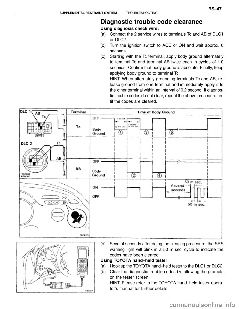
Diagnostic trouble code clearance
Using diagnosis check wire:
(a) Connect the 2 service wires to terminals Tc and AB of DLC1
or DLC2.
(b) Turn the ignition switch to ACC or ON and wait approx. 6
seconds.
(c) Starting with the Tc terminal, apply body ground alternately
to terminal Tc and terminal AB twice each in cycles of 1.0
seconds. Confirm that body ground is absolute. Finally, keep
applying body ground to terminal Tc.
HINT: When alternately grounding terminals Tc and AB, re-
lease ground from one terminal and immediately apply it to
the other terminal within an interval of 0.2 second. If diagnos-
tic trouble codes do not clear, repeat the above procedure un-
til the codes are cleared.
(d) Several seconds after doing the clearing procedure, the SRS
warning light will blink in a 50 m sec. cycle to indicate the
codes have been cleared.
Using TOYOTA hand±held tester:
(a) Hook up the TOYOTA hand±held tester to the DLC1 or DLC2.
(b) Clear the diagnostic trouble codes by following the prompts
on the tester screen.
HINT: Please refer to the TOYOTA hand±held tester opera-
tor 's manual for further details.
± SUPPLEMENTAL RESTRAINT SYSTEMTROUBLESHOOTINGRS±47