Page 118 of 2543

INTRODUCTIONGLOSSARY OF SAE AND TOYOTA TERMS -
IN-7
GLOSSARY OF SAE AND TOYOTA TERMS
This glossary lists all SAE-J1930 terms and abbreviations used in this manual in compliance with SAE
recommendations, as well as their Toyota equivalents.
SAE
ABBREVIATIONSSAE TERMSTOYOTA TERMS
( )--ABBREVIATIONS
A/CAir ConditioningAir Conditioner
ACLAir CleanerAir Cleaner
AIRSecondary Air InjectionAir Injection (AI)
APAccelerator Pedal-
B+Battery Positive Voltage+B, Battery Voltage
BAROBarometric Pressure-
CACCharge Air CoolerIntercooler
CARBCarburetorCarburetor
CFIContinuous Fuel Injection-
CKPCrankshaft PositionCrank Angle
CLClosed LoopClosed Loop
CMPCamshaft PositionCam Angle
CPPClutch Pedal Position-
CTOXContinuous Trap Oxidizer-
CTPClosed Throttle Position-
DFIDirect Fuel Injection (Diesel)Direct Injection (DI)
DIDistributor Ignition-
DLC1
DLC2
DLC3Data Link Connector 1
Data Link Connector 2
Data Link Connector 31: Check Connector
2: Toyota Diagnosis Communication Link (TDCL)
3: OBD II Diagnostic Connector
DTCDiagnostic Trouble CodeDiagnostic Code
DTMDiagnostic Test Mode-
ECLEngine Control Level-
ECMEngine Control ModuleEngine ECU (Electronic Control Unit)
ECTEngine Coolant TemperatureCoolant Temperature, Water Temperature (THW)
EEPROMElectrically Erasable Programmable Read Only
MemoryElectrically Erasable Programmable Read Only Memory
(EEPROM),
Erasable Programmable Read Only Memory(EPROM)
EFEEarly Fuel EvaporationCold Mixture Heater (CMH), Heat Control Valve (HCV)
EGRExhaust Gas RecirculationExhaust Gas Recirculation (EGR)
EIElectronic IgnitionToyota Distributorless Ignition (TDI)
EMEngine ModificationEngine Modification (EM)
EPROMErasable Programmable Read Only MemoryProgrammable Read Only Memory (PROM)
EVAPEvaporative EmissionEvaporative Emission Control (EVAP)
FCFan Control-
FEEPROMFlash Electrically Erasable Programmable
Read Only Memory-
FEPROMFlash Erasable Programmable Read Only Memory-
FFFlexible Fuel-
FPFuel PumpFuel Pump
GENGeneratorAlternator
GNDGroundGround (GND)
HO2SHeated Oxygen SensorHeated Oxygen Sensor (HO2S)
IN016-02
Page 897 of 2543

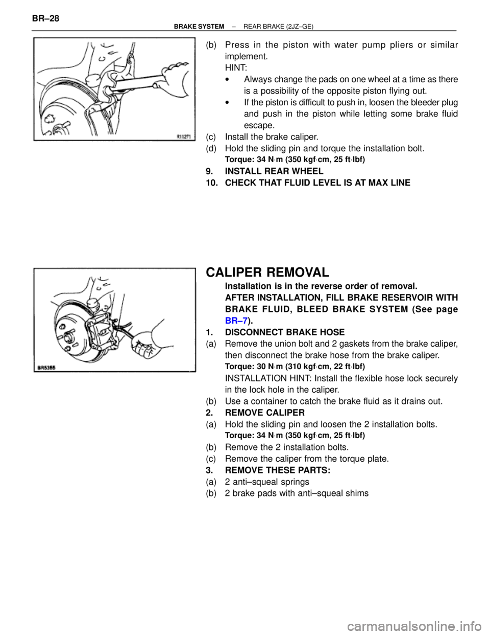
(b) Press in the piston with water pump pliers or similar
implement.
HINT:
wAlways change the pads on one wheel at a time as there
is a possibility of the opposite piston flying out.
wIf the piston is difficult to push in, loosen the bleeder plug
and push in the piston while letting some brake fluid
escape.
(c) Install the brake caliper.
(d) Hold the sliding pin and torque the installation bolt.
Torque: 34 NVm (350 kgfVcm, 25 ftVlbf)
9. INSTALL REAR WHEEL
10. CHECK THAT FLUID LEVEL IS AT MAX LINE
CALIPER REMOVAL
Installation is in the reverse order of removal.
AFTER INSTALLATION, FILL BRAKE RESERVOIR WITH
BRAKE FLUID, BLEED BRAKE SYSTEM (See page
BR±7).
1. DISCONNECT BRAKE HOSE
(a) Remove the union bolt and 2 gaskets from the brake caliper,
then disconnect the brake hose from the brake caliper.
Torque: 30 NVm (310 kgfVcm, 22 ftVlbf)
INSTALLATION HINT: Install the flexible hose lock securely
in the lock hole in the caliper.
(b) Use a container to catch the brake fluid as it drains out.
2. REMOVE CALIPER
(a) Hold the sliding pin and loosen the 2 installation bolts.
Torque: 34 NVm (350 kgfVcm, 25 ftVlbf)
(b) Remove the 2 installation bolts.
(c) Remove the caliper from the torque plate.
3. REMOVE THESE PARTS:
(a) 2 anti±squeal springs
(b) 2 brake pads with anti±squeal shims BR±28
± BRAKE SYSTEMREAR BRAKE (2JZ±GE)
Page 1057 of 2543

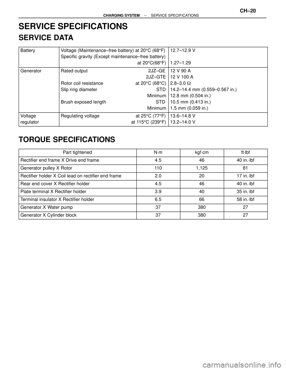
SERVICE SPECIFICATIONS
SERVICE DATA
������� �
������ �
������ �������
Battery���������������� �
��������������� �
��������������� ����������������
Voltage (Maintenance±free battery) at 205C (685F)
Specific gravity (Except maintenance±free battery)
at 205C(685F)��������������� �
�������������� �
�������������� ���������������
12.7±12.9 V
1.27±1.29
������� �
������ �
������ �
������ �
������ �
������ �������
Generator���������������� �
��������������� �
��������������� �
��������������� �
��������������� �
��������������� ����������������
Rated output 2JZ±GE
2JZ±GTE
Rotor coil resistance at 205C (685C)
Slip ring diameter STD
Minimum
Brush exposed length STD
Minimum��������������� �
�������������� �
�������������� �
�������������� �
�������������� �
�������������� ���������������
12 V 90 A
12 V 100 A
2.8±3.0 �
14.2±14.4 mm (0.559±0.567 in.)
12.8 mm (0.504 in.)
10.5 mm (0.413 in.)
1.5 mm (0.059 in.)
������� �
������ �������Voltage
regulator���������������� �
��������������� ����������������Regulating voltage at 255C (775F)
at 1155C (2395F)��������������� �
�������������� ���������������13.6±14.8 V
13.2±14.0 V
TORQUE SPECIFICATIONS
����������������� �����������������Part tightened������� �������NVm������� �������kgfVcm������� �������ftVlbf����������������� �����������������Rectifier end frame X Drive end frame������� �������4.5������� �������46������� �������40 in.Vlbf����������������� �
����������������
�����������������
Generator pulley X Rotor�������
������� �������11 0������� �
������ �������1,125������� �
������ �������81
����������������� �����������������Rectifier holder X Coil lead on rectifier end frame������� �������2.0������� �������20������� �������17 in.Vlbf
����������������� �����������������Rear end cover X Rectifier holder������� �������4.5������� �������46������� �������40 in.Vlbf
����������������� �����������������Plate terminal X Rectifier holder������� �������3.9������� �������40������� �������35 in.Vlbf
����������������� �����������������Terminal insulator X Rectifier holder������� �������6.5������� �������66������� �������58 in.Vlbf
����������������� �����������������Generator X Water pump������� �������37������� �������380������� �������27
����������������� �����������������Generator X Cylinder block������� �������37������� �������380������� �������27
± CHARGING SYSTEMSERVICE SPECIFICATIONSCH±20
Page 1083 of 2543
WATER PUMP
COMPONENTS FOR REMOVAL AND
INSTALLATION
EG±332± ENGINECOOLING SYSTEM
Page 1085 of 2543

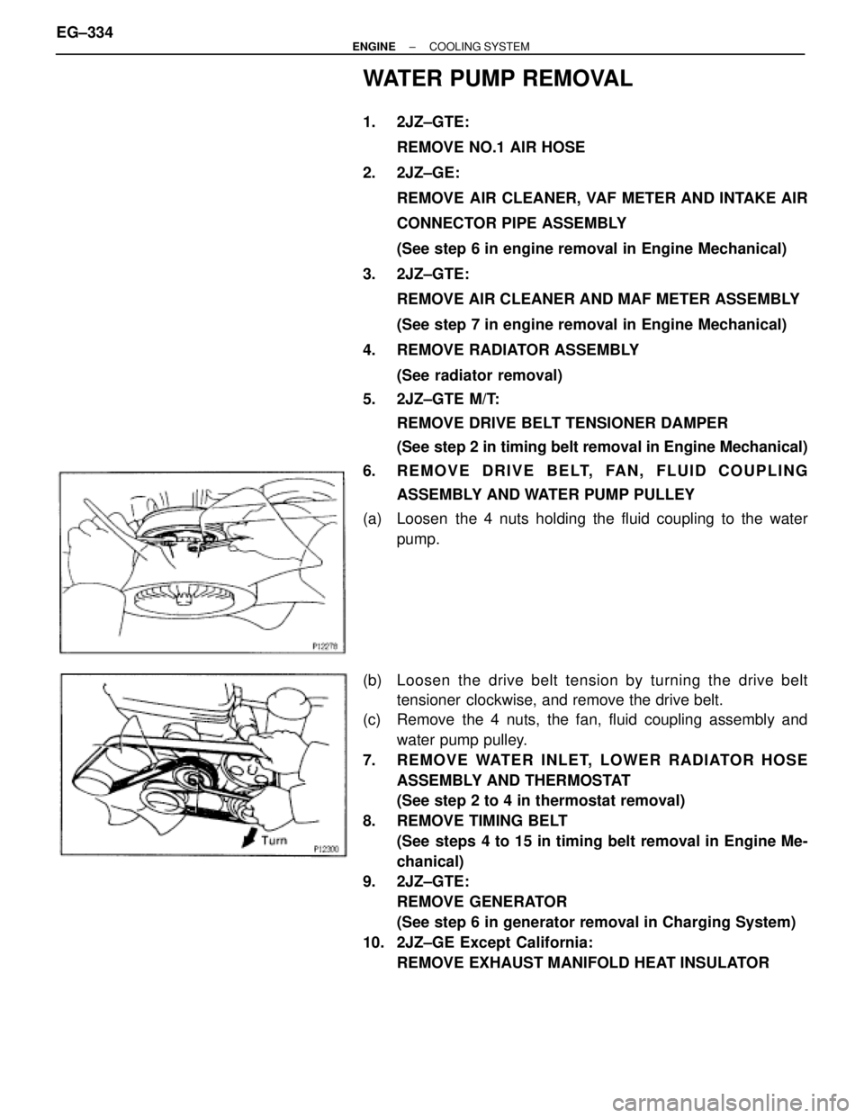
WATER PUMP REMOVAL
1. 2JZ±GTE:
REMOVE NO.1 AIR HOSE
2. 2JZ±GE:
REMOVE AIR CLEANER, VAF METER AND INTAKE AIR
CONNECTOR PIPE ASSEMBLY
(See step 6 in engine removal in Engine Mechanical)
3. 2JZ±GTE:
REMOVE AIR CLEANER AND MAF METER ASSEMBLY
(See step 7 in engine removal in Engine Mechanical)
4. REMOVE RADIATOR ASSEMBLY
(See radiator removal)
5. 2JZ±GTE M/T:
REMOVE DRIVE BELT TENSIONER DAMPER
(See step 2 in timing belt removal in Engine Mechanical)
6. REMOVE DRIVE BELT, FAN, FLUID COUPLING
ASSEMBLY AND WATER PUMP PULLEY
(a) Loosen the 4 nuts holding the fluid coupling to the water
pump.
(b) Loosen the drive belt tension by turning the drive belt
tensioner clockwise, and remove the drive belt.
(c) Remove the 4 nuts, the fan, fluid coupling assembly and
water pump pulley.
7. REMOVE WATER INLET, LOWER RADIATOR HOSE
ASSEMBLY AND THERMOSTAT
(See step 2 to 4 in thermostat removal)
8. REMOVE TIMING BELT
(See steps 4 to 15 in timing belt removal in Engine Me-
chanical)
9. 2JZ±GTE:
REMOVE GENERATOR
(See step 6 in generator removal in Charging System)
10. 2JZ±GE Except California:
REMOVE EXHAUST MANIFOLD HEAT INSULATOR EG±334
± ENGINECOOLING SYSTEM
Page 1086 of 2543
11. 2JZ±GTE:
DISCONNECT TURBO WATER HOSES FROM WATER
OUTLET
12. 2JZ±GE:
REMOVE WATER BYPASS OUTLET AND NO.1 WATER
BYPASS PIPE
(a) Remove the 2 bolts, water bypass outlet and No.1 water
bypass pipe.
(b) Remove the 3 O±rings from the water bypass outlet and No.1
water bypass pipe.
13. 2JZ±GTE:
REMOVE WATER OUTLET AND NO.1 WATER BYPASS
PIPE
(a) Disconnect the ECT sensor and sender gauge connectors.
(b) Remove the 2 bolts, water outlet and gasket.
(c) Remove the No.1 water bypass pipe and 2 O±rings.
14. REMOVE IDLER PULLEY
(See steps 16 in timing belt removal in Engine Mechani-
cal)
15. REMOVE WATER PUMP
(a) 2JZ±GE:
Remove the mounting bolt, and disconnect the engine wire
bracket.
(b) 2JZ±GE:
Loosen the generator mounting nut.
(c) 2JZ±GE:
Remove the generator mounting bolt, and disconnect the
generator from the water pump.
± ENGINECOOLING SYSTEMEG±335
Page 1087 of 2543
(d) Remove the 2 nuts, and disconnect the No.2 water bypass
pipe from the water pump.
(e) 2JZ±GTE:
Disconnect the No.3 turbo water hose from the water pump.
(f) Remove the 6 bolts, water pump and gasket.
(g) Remove the O±ring from the cylinder block.
WATER PUMP COMPONENTS
INSPECTION
1. INSPECT WATER PUMP
Turn the pulley seat, and check that the water pump bearing
is not rough or noisy.
If necessary, replace the water pump.
2. INSPECT FLUID COUPLING
(a) Remove the 4 nuts and fan from the fluid coupling. EG±336
± ENGINECOOLING SYSTEM
Page 1088 of 2543

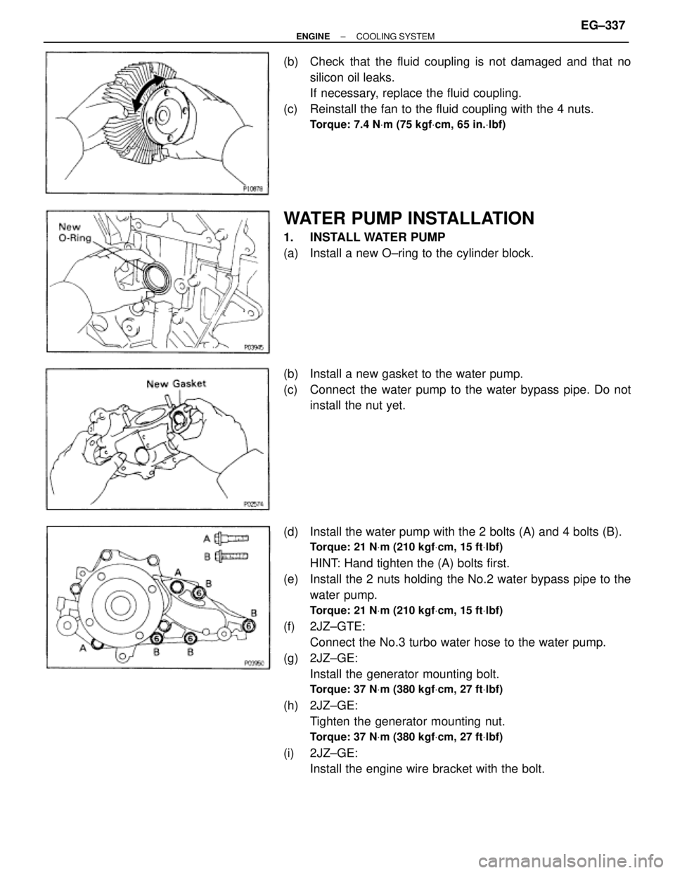
(b) Check that the fluid coupling is not damaged and that no
silicon oil leaks.
If necessary, replace the fluid coupling.
(c) Reinstall the fan to the fluid coupling with the 4 nuts.
Torque: 7.4 NVm (75 kgfVcm, 65 in.Vlbf)
WATER PUMP INSTALLATION
1. INSTALL WATER PUMP
(a) Install a new O±ring to the cylinder block.
(b) Install a new gasket to the water pump.
(c) Connect the water pump to the water bypass pipe. Do not
install the nut yet.
(d) Install the water pump with the 2 bolts (A) and 4 bolts (B).
Torque: 21 NVm (210 kgfVcm, 15 ftVlbf)
HINT: Hand tighten the (A) bolts first.
(e) Install the 2 nuts holding the No.2 water bypass pipe to the
water pump.
Torque: 21 NVm (210 kgfVcm, 15 ftVlbf)
(f) 2JZ±GTE:
Connect the No.3 turbo water hose to the water pump.
(g) 2JZ±GE:
Install the generator mounting bolt.
Torque: 37 NVm (380 kgfVcm, 27 ftVlbf)
(h) 2JZ±GE:
Tighten the generator mounting nut.
Torque: 37 NVm (380 kgfVcm, 27 ftVlbf)
(i) 2JZ±GE:
Install the engine wire bracket with the bolt.
± ENGINECOOLING SYSTEMEG±337