Page 1085 of 2543
WATER PUMP REMOVAL
1. 2JZ±GTE:
REMOVE NO.1 AIR HOSE
2. 2JZ±GE:
REMOVE AIR CLEANER, VAF METER AND INTAKE AIR
CONNECTOR PIPE ASSEMBLY
(See step 6 in engine removal in Engine Mechanical)
3. 2JZ±GTE:
REMOVE AIR CLEANER AND MAF METER ASSEMBLY
(See step 7 in engine removal in Engine Mechanical)
4. REMOVE RADIATOR ASSEMBLY
(See radiator removal)
5. 2JZ±GTE M/T:
REMOVE DRIVE BELT TENSIONER DAMPER
(See step 2 in timing belt removal in Engine Mechanical)
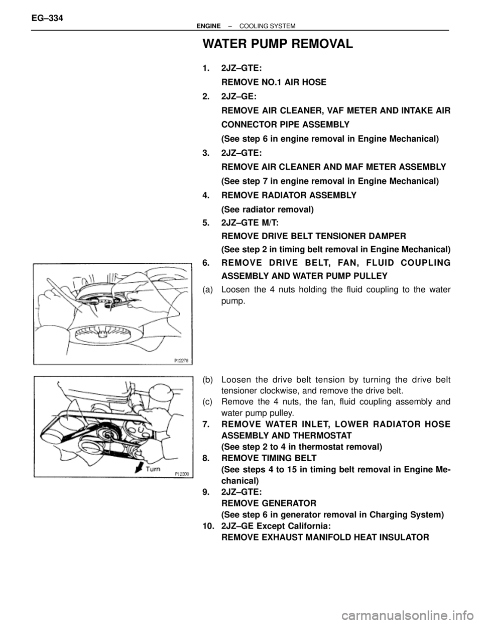
6. REMOVE DRIVE BELT, FAN, FLUID COUPLING
ASSEMBLY AND WATER PUMP PULLEY
(a) Loosen the 4 nuts holding the fluid coupling to the water
pump.
(b) Loosen the drive belt tension by turning the drive belt
tensioner clockwise, and remove the drive belt.
(c) Remove the 4 nuts, the fan, fluid coupling assembly and
water pump pulley.
7. REMOVE WATER INLET, LOWER RADIATOR HOSE
ASSEMBLY AND THERMOSTAT
(See step 2 to 4 in thermostat removal)
8. REMOVE TIMING BELT
(See steps 4 to 15 in timing belt removal in Engine Me-
chanical)
9. 2JZ±GTE:
REMOVE GENERATOR
(See step 6 in generator removal in Charging System)
10. 2JZ±GE Except California:
REMOVE EXHAUST MANIFOLD HEAT INSULATOR EG±334
± ENGINECOOLING SYSTEM
Page 1086 of 2543
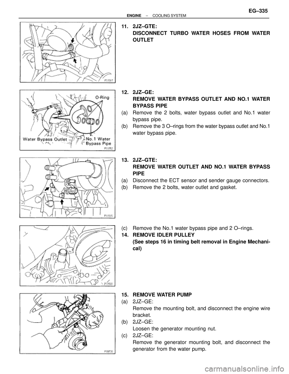
11. 2JZ±GTE:
DISCONNECT TURBO WATER HOSES FROM WATER
OUTLET
12. 2JZ±GE:
REMOVE WATER BYPASS OUTLET AND NO.1 WATER
BYPASS PIPE
(a) Remove the 2 bolts, water bypass outlet and No.1 water
bypass pipe.
(b) Remove the 3 O±rings from the water bypass outlet and No.1
water bypass pipe.
13. 2JZ±GTE:
REMOVE WATER OUTLET AND NO.1 WATER BYPASS
PIPE
(a) Disconnect the ECT sensor and sender gauge connectors.
(b) Remove the 2 bolts, water outlet and gasket.
(c) Remove the No.1 water bypass pipe and 2 O±rings.
14. REMOVE IDLER PULLEY
(See steps 16 in timing belt removal in Engine Mechani-
cal)
15. REMOVE WATER PUMP
(a) 2JZ±GE:
Remove the mounting bolt, and disconnect the engine wire
bracket.
(b) 2JZ±GE:
Loosen the generator mounting nut.
(c) 2JZ±GE:
Remove the generator mounting bolt, and disconnect the
generator from the water pump.
± ENGINECOOLING SYSTEMEG±335
Page 1089 of 2543
2. INSTALL IDLER PULLEY
(See step 2 in timing belt installation in Engine Mechani-
cal)
3. 2JZ±GTE:
INSTALL WATER OUTLET AND NO.1 WATER BYPASS
PIPE
(a) Install 2 new O±rings to the No.1 water bypass pipe.
(b) Apply soapy water to the O±rings.
(c) Install the No.1 water pass pipe to the water pump.
(d) Install a new gasket and the water outlet with the 2 bolts.
Torque: 21 NVm (210 kgfVcm, 15 ftVlbf)
(e) Connect the ECT sensor and sender gauge connectors.
4. 2JZ±GE:
INSTALL WATER BYPASS OUTLET AND NO.1 WATER
BYPASS PIPE
(a) Install 2 new O±rings to the No.1 water bypass pipe.
(b) Install a new O±ring and the water bypass outlet with the 2
bolts.
Torque: 8.8 NVm (90 kgfVcm, 78 in.Vlbf)
5. 2JZ±GTE:
CONNECT TURBO WATER HOSES TO WATER OUTLET
6. 2JZ±GE Except California:
INSTALL EXHAUST MANIFOLD HEAT INSULATOR
7. 2JZ±GTE:
INSTALL GENERATOR
(See generator installation in Charging System)
8. INSTALL TIMING BELT
(See steps 10 to 14 in timing belt installation in Engine
Mechanical)
9. INSTALL WATER INLET AND LOWER RADIATOR HOSE
ASSEMBLY
(See thermostat installation)
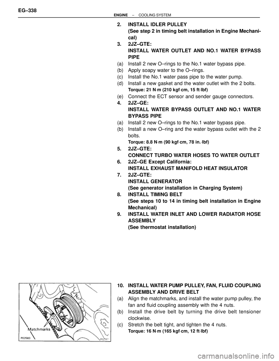
10. INSTALL WATER PUMP PULLEY, FAN, FLUID COUPLING
ASSEMBLY AND DRIVE BELT
(a) Align the matchmarks, and install the water pump pulley, the
fan and fluid coupling assembly with the 4 nuts.
(b) Install the drive belt by turning the drive belt tensioner
clockwise.
(c) Stretch the belt tight, and tighten the 4 nuts.
Torque: 16 NVm (165 kgfVcm, 12 ftVlbf)
EG±338± ENGINECOOLING SYSTEM
Page 1140 of 2543
HIGH±TENSION CORDS INSPECTION
1. REMOVE THROTTLE BODY
(See throttle body removal in SFI System)
2. REMOVE NO.3 TIMING BELT COVER
3. REMOVE CYLINDER HEAD REAR COVER
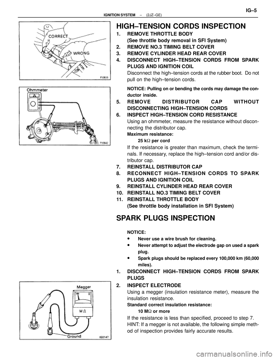
4. DISCONNECT HIGH±TENSION CORDS FROM SPARK
PLUGS AND IGNITION COIL
Disconnect the high±tension cords at the rubber boot. Do not
pull on the high±tension cords.
NOTICE: Pulling on or bending the cords may damage the con-
ductor inside.
5. REMOVE DISTRIBUTOR CAP WITHOUT
DISCONNECTING HIGH±TENSION CORDS
6. INSPECT HIGH±TENSION CORD RESISTANCE
Using an ohmmeter, measure the resistance without discon-
necting the distributor cap.
Maximum resistance:
25 k� per cord
If the resistance is greater than maximum, check the termi-
nals. If necessary, replace the high±tension cord and/or dis-
tributor cap.
7. REINSTALL DISTRIBUTOR CAP
8. RECONNECT HIGH±TENSION CORDS TO SPARK
PLUGS AND IGNITION COIL
9. REINSTALL CYLINDER HEAD REAR COVER
10. REINSTALL NO.3 TIMING BELT COVER
11. REINSTALL THROTTLE BODY
(See throttle body installation in SFI System)
SPARK PLUGS INSPECTION
NOTICE:
wNever use a wire brush for cleaning.
wNever attempt to adjust the electrode gap on used a spark
plug.
wSpark plugs should be replaced every 100,000 km (60,000
miles).
1. DISCONNECT HIGH±TENSION CORDS FROM SPARK
PLUGS
2. INSPECT ELECTRODE
Using a megger (insulation resistance meter), measure the
insulation resistance.
Standard correct insulation resistance:
10 M� or more
If the resistance is less than specified, proceed to step 7.
HINT: If a megger is not available, the following simple meth-
od of inspection provides fairly accurate results.
± IGNITION SYSTEM(2JZ±GE)IG±5
Page 1145 of 2543
HIGH±TENSION CORDS AND CORD
CLAMPS REMOVAL
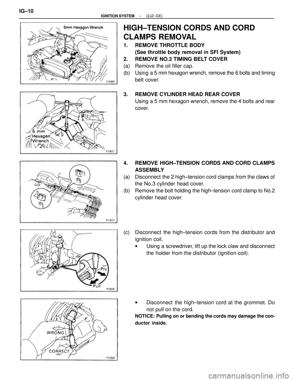
1. REMOVE THROTTLE BODY
(See throttle body removal in SFI System)
2. REMOVE NO.3 TIMING BELT COVER
(a) Remove the oil filler cap.
(b) Using a 5 mm hexagon wrench, remove the 6 bolts and timing
belt cover.
3. REMOVE CYLINDER HEAD REAR COVER
Using a 5 mm hexagon wrench, remove the 4 bolts and rear
cover.
4. REMOVE HIGH±TENSION CORDS AND CORD CLAMPS
ASSEMBLY
(a) Disconnect the 2 high±tension cord clamps from the claws of
the No.3 cylinder head cover.
(b) Remove the bolt holding the high±tension cord clamp to No.2
cylinder head cover.
(c) Disconnect the high±tension cords from the distributor and
ignition coil.
wUsing a screwdriver, lift up the lock claw and disconnect
the holder from the distributor (ignition coil).
wDisconnect the high±tension cord at the grommet. Do
not pull on the cord.
NOTICE: Pulling on or bending the cords may damage the con-
ductor inside.
IG±10± IGNITION SYSTEM(2JZ±GE)
Page 1148 of 2543
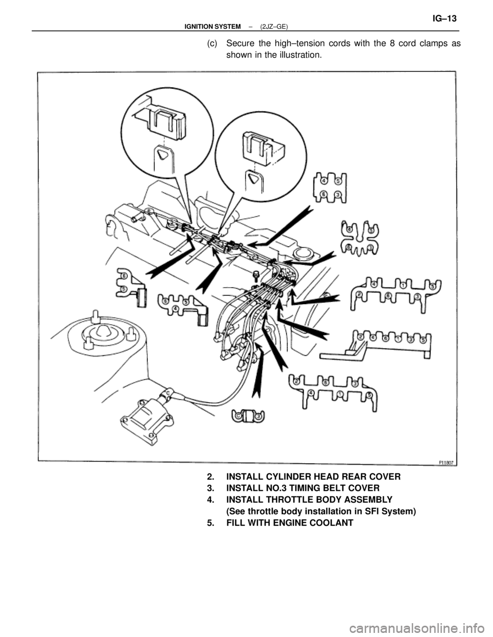
(c) Secure the high±tension cords with the 8 cord clamps as
shown in the illustration.
2. INSTALL CYLINDER HEAD REAR COVER
3. INSTALL NO.3 TIMING BELT COVER
4. INSTALL THROTTLE BODY ASSEMBLY
(See throttle body installation in SFI System)
5. FILL WITH ENGINE COOLANT
± IGNITION SYSTEM(2JZ±GE)IG±13
Page 1151 of 2543
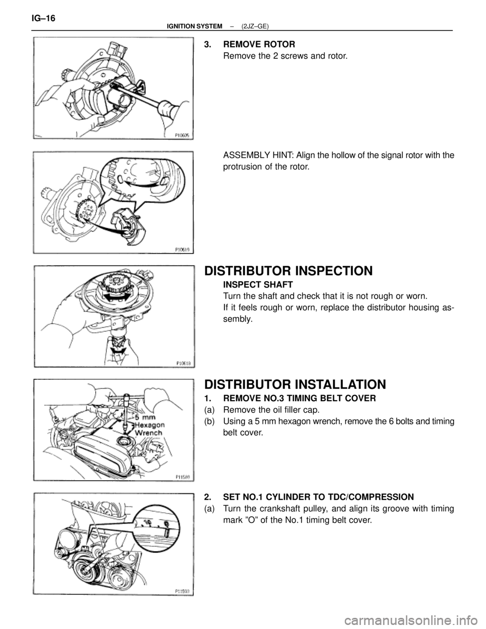
3. REMOVE ROTOR
Remove the 2 screws and rotor.
ASSEMBLY HINT: Align the hollow of the signal rotor with the
protrusion of the rotor.
DISTRIBUTOR INSPECTION
INSPECT SHAFT
Turn the shaft and check that it is not rough or worn.
If it feels rough or worn, replace the distributor housing as-
sembly.
DISTRIBUTOR INSTALLATION
1. REMOVE NO.3 TIMING BELT COVER
(a) Remove the oil filler cap.
(b) Using a 5 mm hexagon wrench, remove the 6 bolts and timing
belt cover.
2. SET NO.1 CYLINDER TO TDC/COMPRESSION
(a) Turn the crankshaft pulley, and align its groove with timing
mark ºOº of the No.1 timing belt cover. IG±16
± IGNITION SYSTEM(2JZ±GE)
Page 1152 of 2543
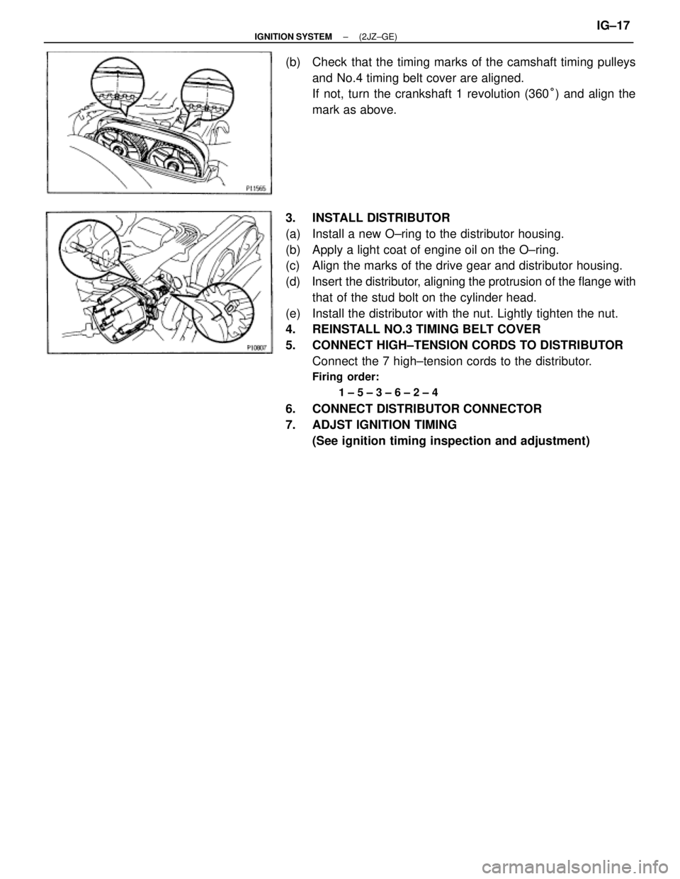
(b) Check that the timing marks of the camshaft timing pulleys
and No.4 timing belt cover are aligned.
If not, turn the crankshaft 1 revolution (360°) and align the
mark as above.
3. INSTALL DISTRIBUTOR
(a) Install a new O±ring to the distributor housing.
(b) Apply a light coat of engine oil on the O±ring.
(c) Align the marks of the drive gear and distributor housing.
(d) Insert the distributor, aligning the protrusion of the flange with
that of the stud bolt on the cylinder head.
(e) Install the distributor with the nut. Lightly tighten the nut.
4. REINSTALL NO.3 TIMING BELT COVER
5. CONNECT HIGH±TENSION CORDS TO DISTRIBUTOR
Connect the 7 high±tension cords to the distributor.
Firing order:
1 ± 5 ± 3 ± 6 ± 2 ± 4
6. CONNECT DISTRIBUTOR CONNECTOR
7. ADJST IGNITION TIMING
(See ignition timing inspection and adjustment)
± IGNITION SYSTEM(2JZ±GE)IG±17