1995 TOYOTA SUPRA seats
[x] Cancel search: seatsPage 862 of 2543
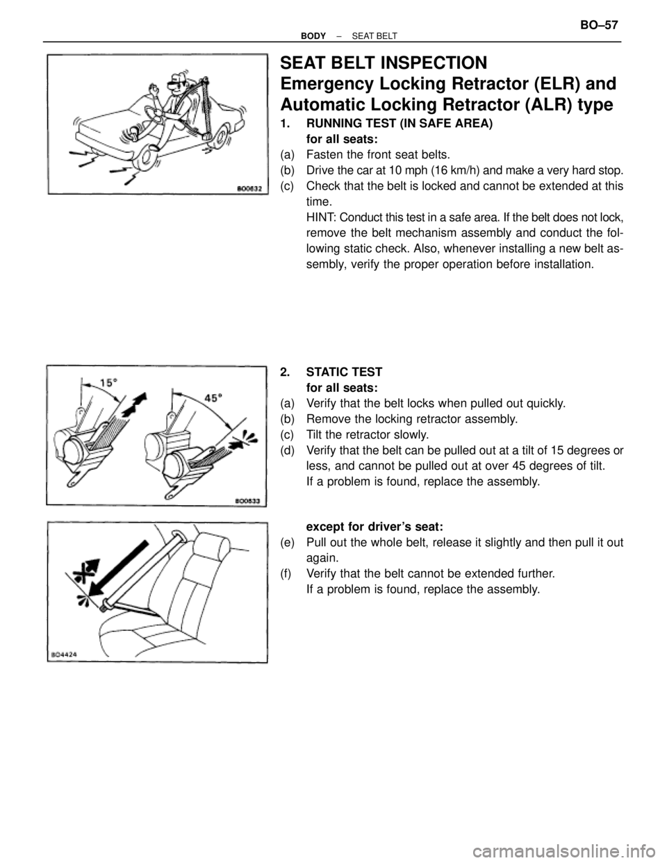
SEAT BELT INSPECTION
Emergency Locking Retractor (ELR) and
Automatic Locking Retractor (ALR) type
1. RUNNING TEST (IN SAFE AREA)
for all seats:
(a) Fasten the front seat belts.
(b) Drive the car at 10 mph (16 km/h) and make a very hard stop.
(c) Check that the belt is locked and cannot be extended at this
time.
HINT: Conduct this test in a safe area. If the belt does not lock,
remove the belt mechanism assembly and conduct the fol-
lowing static check. Also, whenever installing a new belt as-
sembly, verify the proper operation before installation.
2. STATIC TEST
for all seats:
(a) Verify that the belt locks when pulled out quickly.
(b) Remove the locking retractor assembly.
(c) Tilt the retractor slowly.
(d) Verify that the belt can be pulled out at a tilt of 15 degrees or
less, and cannot be pulled out at over 45 degrees of tilt.
If a problem is found, replace the assembly.
except for driver's seat:
(e) Pull out the whole belt, release it slightly and then pull it out
again.
(f) Verify that the belt cannot be extended further.
If a problem is found, replace the assembly.
± BODYSEAT BELTBO±57
Page 1249 of 2543
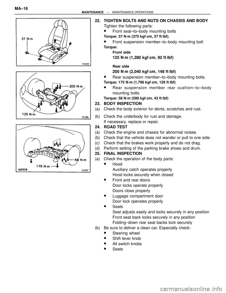
22. TIGHTEN BOLTS AND NUTS ON CHASSIS AND BODY
Tighten the following parts:
wFront seat±to±body mounting bolts
Torque: 37 NVm (375 kgfVcm, 27 ftVlbf).
wFront suspension member±to±body mounting bolt
Torque:
Front side
125 NVm (1,280 kgfVcm, 92 ftVlbf)
Rear side
200 NVm (2,040 kgfVcm, 148 ftVlbf)
wRear suspension member±to±body mounting bolts.
Torque: 175 NVm (1,790 kgfVcm, 129 ftVlbf)
wRear suspension member rear cushion±to±body
mounting bolts
Torque: 58 NVm (590 kgfVcm, 43 ftVlbf)
23. BODY INSPECTION
(a) Check the body exterior for dents, scratches and rust.
(b) Check the underbody for rust and damage.
If necessary, replace or repair.
24. ROAD TEST
(a) Check the engine and chassis for abnormal noises.
(b) Check that the vehicle does not wander or pull to one side.
(c) Check that the brakes work properly and do not drag.
(d) Perform setting of the parking brake shoes and drum.
25. FINAL INSPECTION
(a) Check the operation of the body parts:
wHood
Auxiliary catch operates properly
Hood locks securely when closed
wFront and rear doors
Door locks operate properly
Doors close properly
wLuggage compartment door
Door lock operates properly
wSeats
Seat adjusts easily and locks securely in any position
Front seat back locks securely in any position
Folding±down rear seat backs lock securely
(b) Be sure to deliver a clean car. Especially check:
wSteering wheel
wShift lever knob
wAll switch knobs
wSeats MA±16
± MAINTENANCEMAINTENANCE OPERATIONS
Page 1250 of 2543

There are some maintenance and inspection
items which are considered to be the owner's re-
sponsibility. They can be performed by the owner
or be can have them done at a service shop.
These items include those which should be
checked on a daily basis, those which, in most
cases, do not require (special) tools and those
which are considered to be reasonable for the
owner to perform. Items and procedures for gen-
eral maintenance are as follows:
OUTSIDE VEHICLE
1. TIRES
(a) Check the pressure with a gauge. Adjust if
necessary.
(b) Check for cuts, damage, uneven or excessive
wear.
2. WHEEL NUTS
When checking the tires, check the nuts for
looseness or for missing nuts. If necessary,
tighten them.
3. WINDSHIELD WIPER BLADES
Check for wear or cracks whenever they do not
wipe clean. Replace if necessary.
4. FLUID LEAKS
(a) Check underneath for leaking fuel, oil, water or
other fluid.
(b) If you smell gasoline fumes or notice any leak,
have the cause found and corrected.
5. DOORS AND ENGINE HOOD
(a) Check that all doors including the trunk lid
operate smoothly, and that all latches lock
securely.
(b) Check that the engine hood secondary latch
secures the hood from opening when the
primary latch is released.
INSIDE VEHICLE
6. LIGHTS
(a) C h e c k t h a t t h e headlights, stop lights,
tail±lights, turn signal lights, and other lights
are all working.
(b) Check the headlight aiming.7. WARNING LIGHT AND BUZZERS
Check that all warning lights and buzzers
function properly.
8. HORN
Check that it is working.
9. WINDSHIELD GLASS
Check for scratches, pits or abrasions.
10. WINDSHIELD WIPER AND WASHER
(a) Check operation of the wipers and washer.
(b) Check that the wipers do not streak.
11. WINDSHIELD DEFROSTER
Check that the air comes out from the defrost-
er outlet when operating the heater air condi-
tioner at defroster mode.
12. REAR VIEW MIRROR
Check that it is mounted securely.
13. SUN VISORS
Check that they move freely and are
mounted securely.
14. STEERING WHEEL
Check that it has the specified freeplay. Be
alert for changes in steering condition, such
as excessive steering effort, excessive free-
play or strange noise.
15. SEATS
(a) Check that all front seat controls such as seat
adjusters, seatback recliner, etc. operate
smoothly.
(b) Check that all latches lock securely in any
position.
(c) Check that the locks hold securely in any
latched position.
(d) Check that the head restraints move up and
down smoothly and that the locks hold
securely in any latched position.
(e) For folding±down rear seat backs, check that
the latches lock securely.
16. SEAT BELTS
(a) Check that the seat belt system such as
buckles, retractors and anchors operate
properly and smoothly.
(b) Check that the belt webbing is not cut, frayed,
worn or damaged.
17. ACCELERATOR PEDAL
Check the pedal for smooth operation and
uneven pedal effort or catching.
GENERAL MAINTENANCE
± MAINTENANCEGENERAL MAINTENANCEMA±17
Page 1364 of 2543
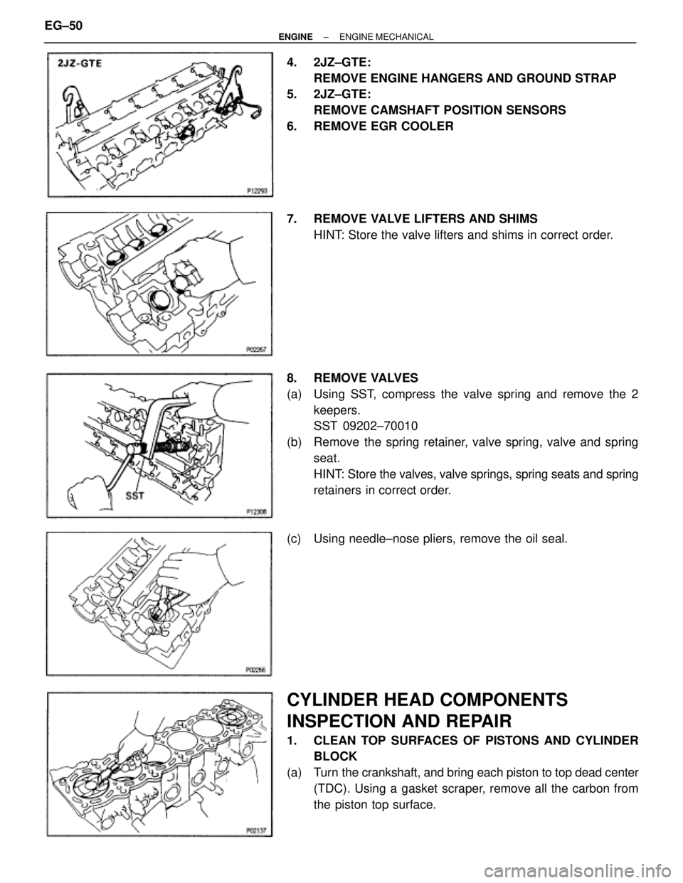
4. 2JZ±GTE:
REMOVE ENGINE HANGERS AND GROUND STRAP
5. 2JZ±GTE:
REMOVE CAMSHAFT POSITION SENSORS
6. REMOVE EGR COOLER
7. REMOVE VALVE LIFTERS AND SHIMS
HINT: Store the valve lifters and shims in correct order.
8. REMOVE VALVES
(a) Using SST, compress the valve spring and remove the 2
keepers.
SST 09202±70010
(b) Remove the spring retainer, valve spring, valve and spring
seat.
HINT: Store the valves, valve springs, spring seats and spring
retainers in correct order.
(c) Using needle±nose pliers, remove the oil seal.
CYLINDER HEAD COMPONENTS
INSPECTION AND REPAIR
1. CLEAN TOP SURFACES OF PISTONS AND CYLINDER
BLOCK
(a) Turn the crankshaft, and bring each piston to top dead center
(TDC). Using a gasket scraper, remove all the carbon from
the piston top surface. EG±50
± ENGINEENGINE MECHANICAL
Page 1369 of 2543
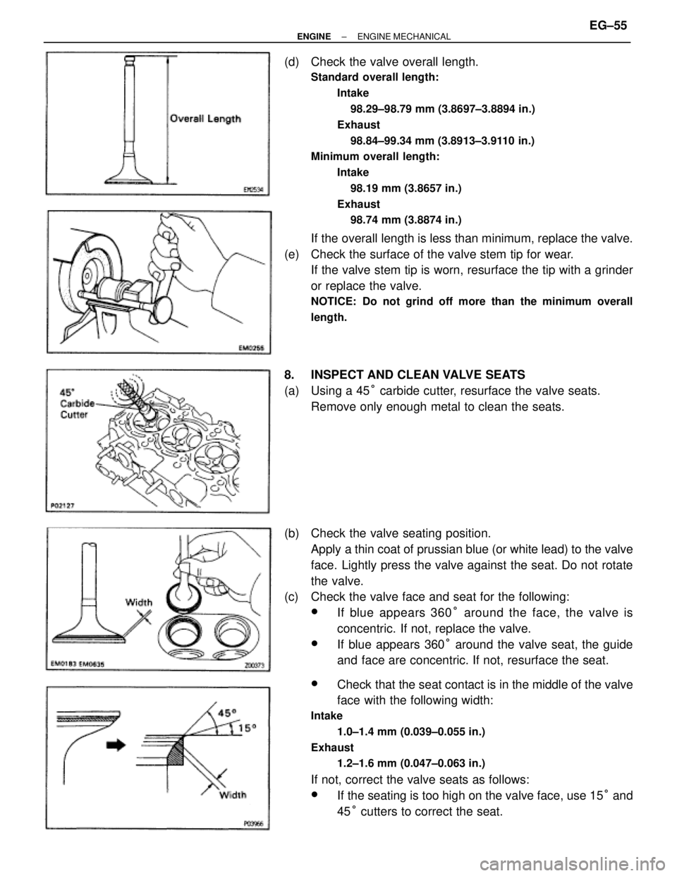
(d) Check the valve overall length.
Standard overall length:
Intake
98.29±98.79 mm (3.8697±3.8894 in.)
Exhaust
98.84±99.34 mm (3.8913±3.9110 in.)
Minimum overall length:
Intake
98.19 mm (3.8657 in.)
Exhaust
98.74 mm (3.8874 in.)
If the overall length is less than minimum, replace the valve.
(e) Check the surface of the valve stem tip for wear.
If the valve stem tip is worn, resurface the tip with a grinder
or replace the valve.
NOTICE: Do not grind off more than the minimum overall
length.
8. INSPECT AND CLEAN VALVE SEATS
(a) Using a 45° carbide cutter, resurface the valve seats.
Remove only enough metal to clean the seats.
(b) Check the valve seating position.
Apply a thin coat of prussian blue (or white lead) to the valve
face. Lightly press the valve against the seat. Do not rotate
the valve.
(c) Check the valve face and seat for the following:
wIf blue appears 360° around the face, the valve is
concentric. If not, replace the valve.
wIf blue appears 360° around the valve seat, the guide
and face are concentric. If not, resurface the seat.
wCheck that the seat contact is in the middle of the valve
face with the following width:
Intake
1.0±1.4 mm (0.039±0.055 in.)
Exhaust
1.2±1.6 mm (0.047±0.063 in.)
If not, correct the valve seats as follows:
wIf the seating is too high on the valve face, use 15° and
45° cutters to correct the seat.
± ENGINEENGINE MECHANICALEG±55
Page 1667 of 2543
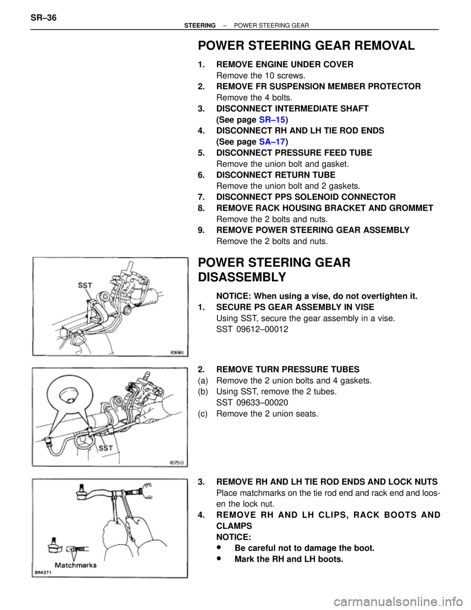
POWER STEERING GEAR REMOVAL
1. REMOVE ENGINE UNDER COVER
Remove the 10 screws.
2. REMOVE FR SUSPENSION MEMBER PROTECTOR
Remove the 4 bolts.
3. DISCONNECT INTERMEDIATE SHAFT
(See page SR±15)
4. DISCONNECT RH AND LH TIE ROD ENDS
(See page SA±17)
5. DISCONNECT PRESSURE FEED TUBE
Remove the union bolt and gasket.
6. DISCONNECT RETURN TUBE
Remove the union bolt and 2 gaskets.
7. DISCONNECT PPS SOLENOID CONNECTOR
8. REMOVE RACK HOUSING BRACKET AND GROMMET
Remove the 2 bolts and nuts.
9. REMOVE POWER STEERING GEAR ASSEMBLY
Remove the 2 bolts and nuts.
POWER STEERING GEAR
DISASSEMBLY
NOTICE: When using a vise, do not overtighten it.
1. SECURE PS GEAR ASSEMBLY IN VISE
Using SST, secure the gear assembly in a vise.
SST 09612±00012
2. REMOVE TURN PRESSURE TUBES
(a) Remove the 2 union bolts and 4 gaskets.
(b) Using SST, remove the 2 tubes.
SST 09633±00020
(c) Remove the 2 union seats.
3. REMOVE RH AND LH TIE ROD ENDS AND LOCK NUTS
Place matchmarks on the tie rod end and rack end and loos-
en the lock nut.
4. REMOVE RH AND LH CLIPS, RACK BOOTS AND
CLAMPS
NOTICE:
wBe careful not to damage the boot.
wMark the RH and LH boots. SR±36
± STEERINGPOWER STEERING GEAR
Page 1674 of 2543
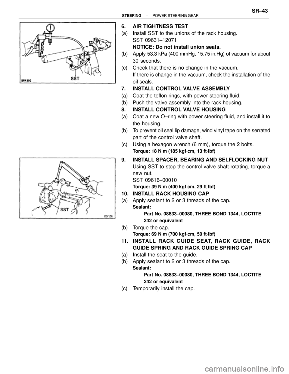
6. AIR TIGHTNESS TEST
(a) Install SST to the unions of the rack housing.
SST 09631±12071
NOTICE: Do not install union seats.
(b) Apply 53.3 kPa (400 mmHg, 15.75 in.Hg) of vacuum for about
30 seconds.
(c) Check that there is no change in the vacuum.
If there is change in the vacuum, check the installation of the
oil seals.
7. INSTALL CONTROL VALVE ASSEMBLY
(a) Coat the teflon rings, with power steering fluid.
(b) Push the valve assembly into the rack housing.
8. INSTALL CONTROL VALVE HOUSING
(a) Coat a new O±ring with power steering fluid, and install it to
the housing.
(b) To prevent oil seal lip damage, wind vinyl tape on the serrated
part of the control valve shaft.
(c) Using a hexagon wrench (6 mm), torque the 2 bolts.
Torque: 18 NVm (185 kgfVcm, 13 ftVlbf)
9. INSTALL SPACER, BEARING AND SELFLOCKING NUT
Using SST to stop the control valve shaft rotating, torque a
new nut.
SST 09616±00010
Torque: 39 NVm (400 kgfVcm, 29 ftVlbf)
10. INSTALL RACK HOUSING CAP
(a) Apply sealant to 2 or 3 threads of the cap.
Sealant:
Part No. 08833±00080, THREE BOND 1344, LOCTITE
242 or equivalent
(b) Torque the cap.
Torque: 69 NVm (700 kgfVcm, 50 ftVlbf)
11. INSTALL RACK GUIDE SEAT, RACK GUIDE, RACK
GUIDE SPRING AND RACK GUIDE SPRING CAP
(a) Install the seat to the guide.
(b) Apply sealant to 2 or 3 threads of the cap.
Sealant:
Part No. 08833±00080, THREE BOND 1344, LOCTITE
242 or equivalent
(c) Temporarily install the cap.
± STEERINGPOWER STEERING GEARSR±43
Page 1676 of 2543
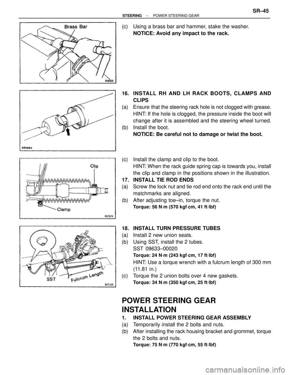
(c) Using a brass bar and hammer, stake the washer.
NOTICE: Avoid any impact to the rack.
16. INS TALL RH AND LH RACK BO O TS , CLAMP S AND
CLIPS
(a) Ensure that the steering rack hole is not clogged with grease.
HINT: If the hole is clogged, the pressure inside the boot will
change after it is assembled and the steering wheel turned.
(b) Install the boot.
NOTICE: Be careful not to damage or twist the boot.
(c) Install the clamp and clip to the boot.
HINT: When the rack guide spring cap is towards you, install
the clip and clamp in the positions shown in the illustration.
17. INSTALL TIE ROD ENDS
(a) Screw the lock nut and tie rod end onto the rack end until the
matchmarks are aligned.
(b) After adjusting toe±in, torque the nut.
Torque: 56 NVm (570 kgfVcm, 41 ftVlbf)
18. INSTALL TURN PRESSURE TUBES
(a) Install 2 new union seats.
(b) Using SST, install the 2 tubes.
SST 09633±00020
Torque: 24 NVm (243 kgfVcm, 17 ftVlbf)
HINT: Use a torque wrench with a fulcrum length of 300 mm
(11.81 in.)
(c) Torque the 2 union bolts over 4 new gaskets.
Torque: 34 NVm (350 kgfVcm, 25 ftVlbf)
POWER STEERING GEAR
INSTALLATION
1. INSTALL POWER STEERING GEAR ASSEMBLY
(a) Temporarily install the 2 bolts and nuts.
(b) After installing the rack housing bracket and grommet, torque
the 2 bolts and nuts.
Torque: 75 NVm (770 kgfVcm, 55 ftVlbf)
± STEERINGPOWER STEERING GEARSR±45