Page 1158 of 2543
6. CLEAN SPARK PLUGS
If the electrode has traces of wet carbon, allow it to dry and
then clean with a spark plug cleaner.
Air pressure:
Below 588 kPa (6 kgf/cm
2, 85 psi)
Duration:
20 seconds or less
HINT: If there are traces of oil, remove it with gasoline before
using the spark plug cleaner.
7. REINSTALL SPARK PLUGS
Torque: 18 NVm (180 kgfVcm, 13 ftVlbf)
8. REINSTALL IGNITION COILS ASSEMBLIES
(See ignition coils installation)
IGNITION COIL INSPECTION
NOTICE: ºColdº and ºHotº in the following sentences express
the temperature of the coils themselves. ºColdº is from ±105C
(145F) to 505C (1225F) and ºHotº is from 505C (1225F) to 1005C
(2125F).
1. REMOVE NO.3 TIMING BELT COVER
2. DISCONNECT IGNITION COIL CONNECTORS
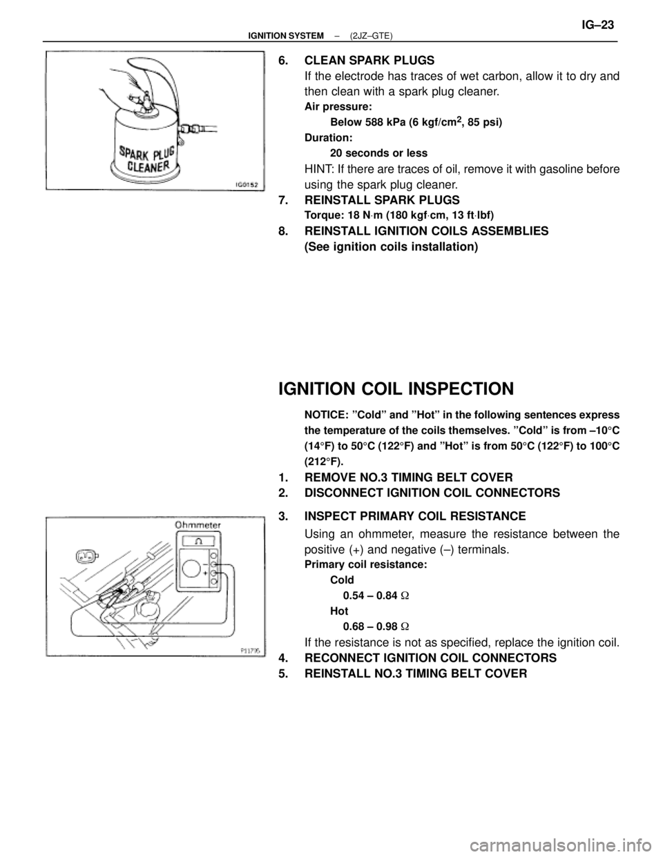
3. INSPECT PRIMARY COIL RESISTANCE
Using an ohmmeter, measure the resistance between the
positive (+) and negative (±) terminals.
Primary coil resistance:
Cold
0.54 ± 0.84 �
Hot
0.68 ± 0.98 �
If the resistance is not as specified, replace the ignition coil.
4. RECONNECT IGNITION COIL CONNECTORS
5. REINSTALL NO.3 TIMING BELT COVER
± IGNITION SYSTEM(2JZ±GTE)IG±23
Page 1161 of 2543
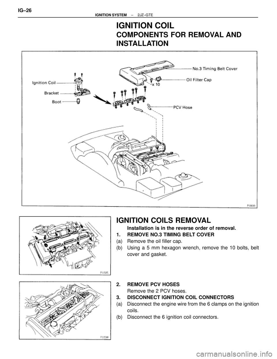
IGNITION COIL
COMPONENTS FOR REMOVAL AND
INSTALLATION
IGNITION COILS REMOVAL
Installation is in the reverse order of removal.
1. REMOVE NO.3 TIMING BELT COVER
(a) Remove the oil filler cap.
(b) Using a 5 mm hexagon wrench, remove the 10 bolts, belt
cover and gasket.
2. REMOVE PCV HOSES
Remove the 2 PCV hoses.
3. DISCONNECT IGNITION COIL CONNECTORS
(a) Disconnect the engine wire from the 6 clamps on the ignition
coils.
(b) Disconnect the 6 ignition coil connectors. IG±26
± IGNITION SYSTEM2JZ±GTE
Page 1219 of 2543
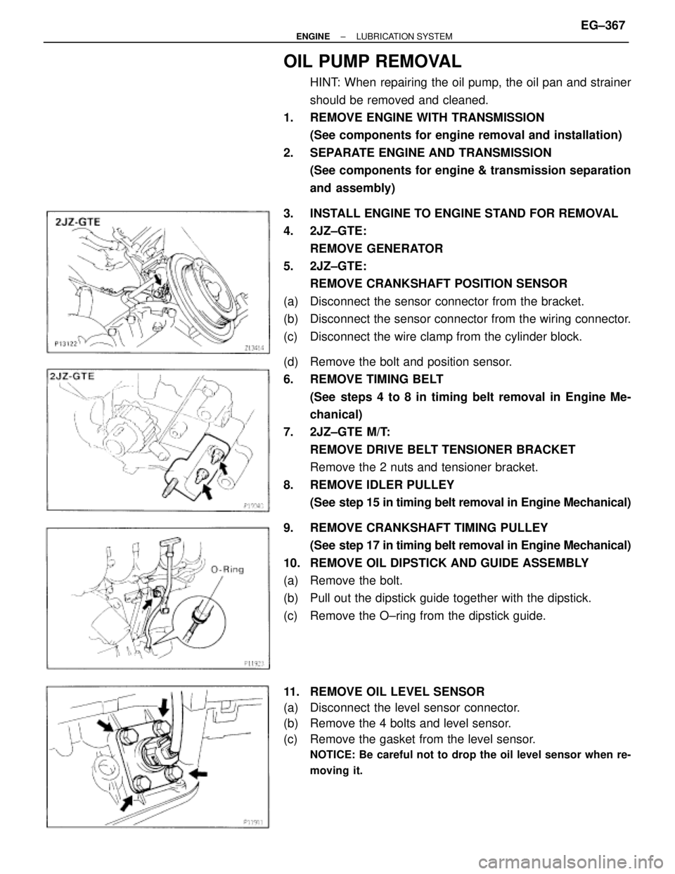
OIL PUMP REMOVAL
HINT: When repairing the oil pump, the oil pan and strainer
should be removed and cleaned.
1. REMOVE ENGINE WITH TRANSMISSION
(See components for engine removal and installation)
2. SEPARATE ENGINE AND TRANSMISSION
(See components for engine & transmission separation
and assembly)
3. INSTALL ENGINE TO ENGINE STAND FOR REMOVAL
4. 2JZ±GTE:
REMOVE GENERATOR
5. 2JZ±GTE:
REMOVE CRANKSHAFT POSITION SENSOR
(a) Disconnect the sensor connector from the bracket.
(b) Disconnect the sensor connector from the wiring connector.
(c) Disconnect the wire clamp from the cylinder block.
(d) Remove the bolt and position sensor.
6. REMOVE TIMING BELT
(See steps 4 to 8 in timing belt removal in Engine Me-
chanical)
7. 2JZ±GTE M/T:
REMOVE DRIVE BELT TENSIONER BRACKET
Remove the 2 nuts and tensioner bracket.
8. REMOVE IDLER PULLEY
(See step 15 in timing belt removal in Engine Mechanical)
9. REMOVE CRANKSHAFT TIMING PULLEY
(See step 17 in timing belt removal in Engine Mechanical)
10. REMOVE OIL DIPSTICK AND GUIDE ASSEMBLY
(a) Remove the bolt.
(b) Pull out the dipstick guide together with the dipstick.
(c) Remove the O±ring from the dipstick guide.
11. REMOVE OIL LEVEL SENSOR
(a) Disconnect the level sensor connector.
(b) Remove the 4 bolts and level sensor.
(c) Remove the gasket from the level sensor.
NOTICE: Be careful not to drop the oil level sensor when re-
moving it.
± ENGINELUBRICATION SYSTEMEG±367
Page 1227 of 2543
6. INSTALL OIL STRAINER
Install a new gasket and the oil strainer with the bolt and 2
nuts.
Torque: 8.8 NVm (90 kgfVcm, 78 in.Vlbf)
7. INSTALL NO.2 OIL PAN
(a) Remove any old packing (FIPG) material and be careful not
to drop any oil on the contact surfaces of the No.1 and No.2
oil pans.
wUsing a razor blade and gasket scraper, remove all the
old packing (FIPG) material from the gasket surfaces
and sealing groove.
wThoroughly clean all components to remove all the
debris.
wUsing a non±residue solvent, clean both sealing
surfaces.
NOTICE: Do not use a solvent which will affect the painted sur-
faces.
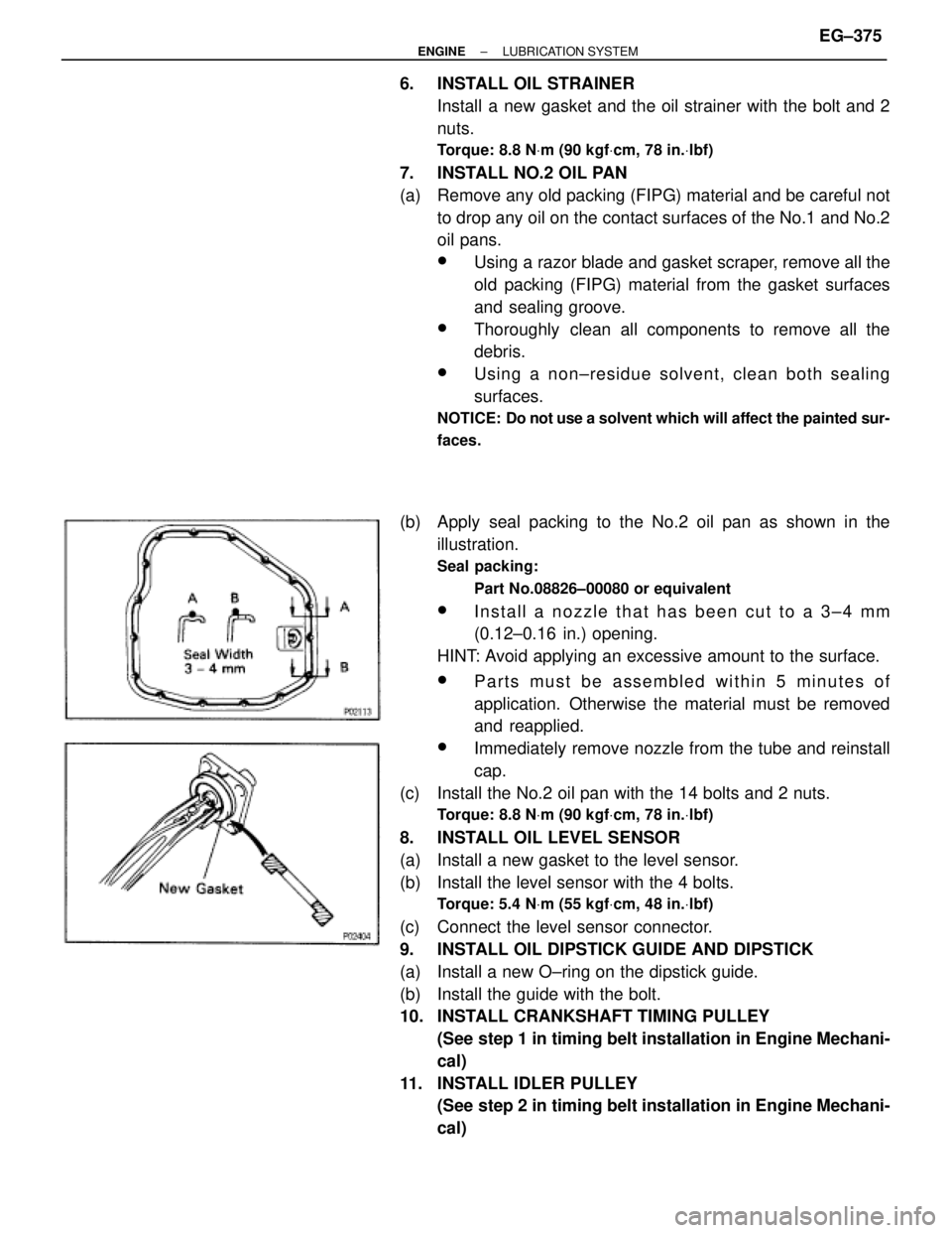
(b) Apply seal packing to the No.2 oil pan as shown in the
illustration.
Seal packing:
Part No.08826±00080 or equivalent
wInstall a nozzle that has been cut to a 3±4 mm
(0.12±0.16 in.) opening.
HINT: Avoid applying an excessive amount to the surface.
wParts must be assembled within 5 minutes of
application. Otherwise the material must be removed
and reapplied.
wImmediately remove nozzle from the tube and reinstall
cap.
(c) Install the No.2 oil pan with the 14 bolts and 2 nuts.
Torque: 8.8 NVm (90 kgfVcm, 78 in.Vlbf)
8. INSTALL OIL LEVEL SENSOR
(a) Install a new gasket to the level sensor.
(b) Install the level sensor with the 4 bolts.
Torque: 5.4 NVm (55 kgfVcm, 48 in.Vlbf)
(c) Connect the level sensor connector.
9. INSTALL OIL DIPSTICK GUIDE AND DIPSTICK
(a) Install a new O±ring on the dipstick guide.
(b) Install the guide with the bolt.
10. INSTALL CRANKSHAFT TIMING PULLEY
(See step 1 in timing belt installation in Engine Mechani-
cal)
11. INSTALL IDLER PULLEY
(See step 2 in timing belt installation in Engine Mechani-
cal)
± ENGINELUBRICATION SYSTEMEG±375
Page 1228 of 2543
12. 2JZ±GTE M/T:
INSTALL DRIVE BELT TENSIONER BRACKET
Torque: 27 NVm (280 kgfVcm, 20 ftVlbf)
13. INSTALL TIMING BELT
(See step 3 in timing belt installation in Engine Mechani-
cal)
14. 2JZ±GTE:
INSTALL CRANKSHAFT POSITION SENSOR
Torque: 8.8 NVm (90 kgfVcm, 78 in.Vlbf)
15. 2JZ±GTE:
INSTALL GENERATOR
16. REMOVE ENGINE STAND FROM ENGINE
17. ASSEMBLY ENGINE AND TRANSMISSION
(See components for engine removal & transmission
separation and assembly)
18. INSTALL ENGINE WITH TRANSMISSION
(See components for engine removal and installation)
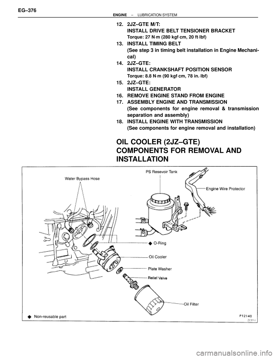
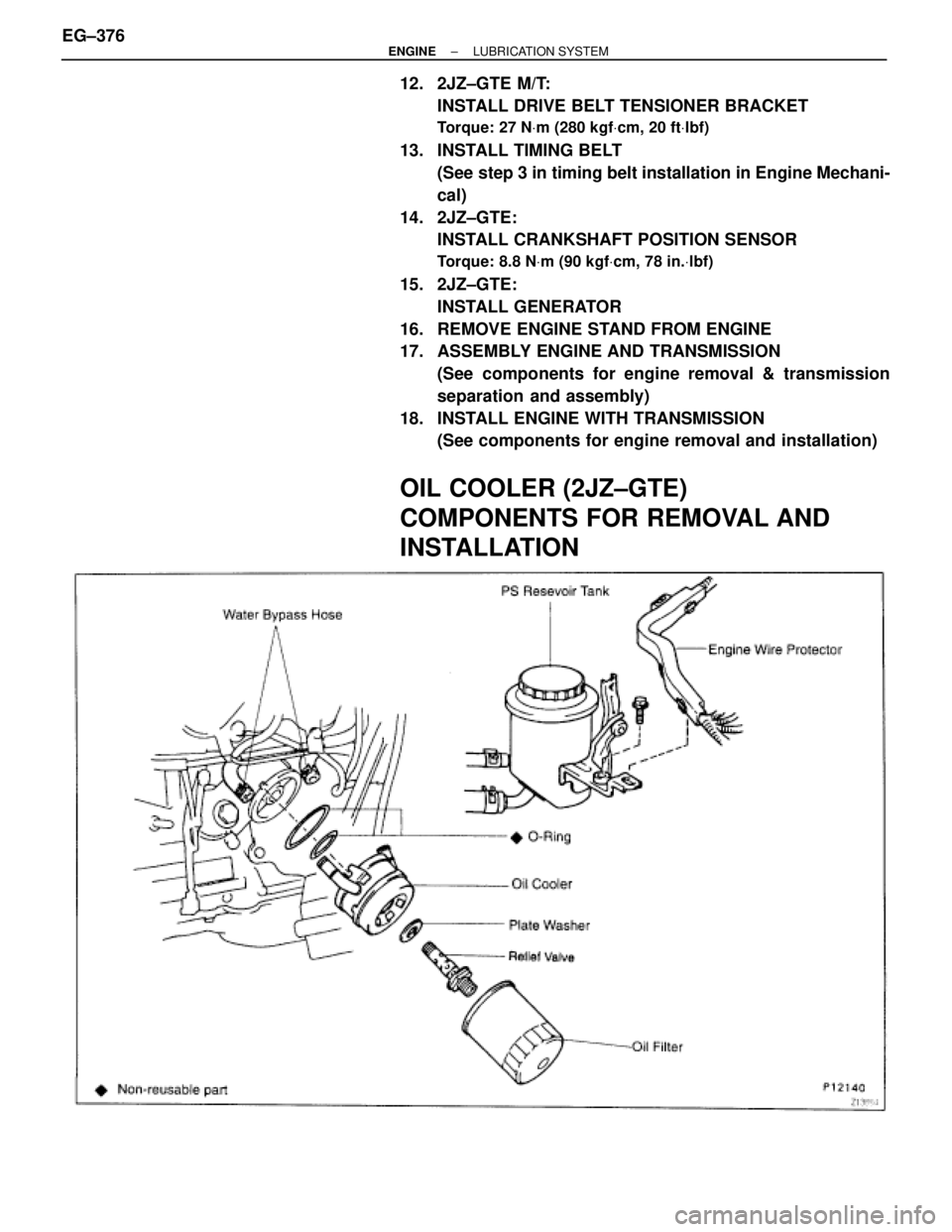
OIL COOLER (2JZ±GTE)
COMPONENTS FOR REMOVAL AND
INSTALLATION
EG±376± ENGINELUBRICATION SYSTEM
Page 1229 of 2543
12. 2JZ±GTE M/T:
INSTALL DRIVE BELT TENSIONER BRACKET
Torque: 27 NVm (280 kgfVcm, 20 ftVlbf)
13. INSTALL TIMING BELT
(See step 3 in timing belt installation in Engine Mechani-
cal)
14. 2JZ±GTE:
INSTALL CRANKSHAFT POSITION SENSOR
Torque: 8.8 NVm (90 kgfVcm, 78 in.Vlbf)
15. 2JZ±GTE:
INSTALL GENERATOR
16. REMOVE ENGINE STAND FROM ENGINE
17. ASSEMBLY ENGINE AND TRANSMISSION
(See components for engine removal & transmission
separation and assembly)
18. INSTALL ENGINE WITH TRANSMISSION
(See components for engine removal and installation)
OIL COOLER (2JZ±GTE)
COMPONENTS FOR REMOVAL AND
INSTALLATION
EG±376± ENGINELUBRICATION SYSTEM
Page 1239 of 2543
MAINTENANCE OPERATIONS
ENGINE
Cold Engine Operations
1. REPLACE TIMING BELT
(See timing belt removal and installation in Engine Me-
chanical)
2. INSPECT DRIVE BELT
(See step 3 in on±vehicle insection in Charging System)
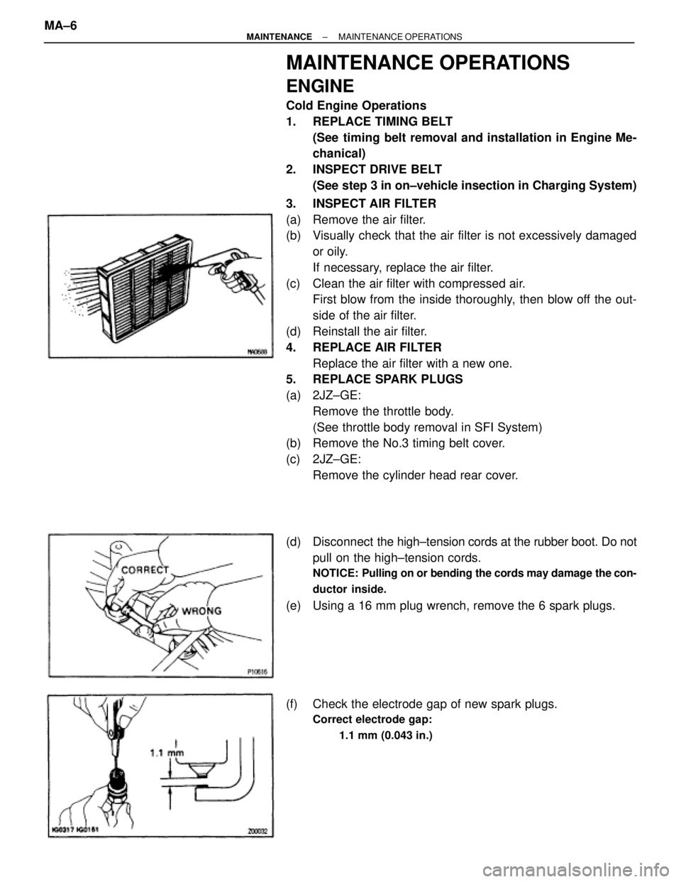
3. INSPECT AIR FILTER
(a) Remove the air filter.
(b) Visually check that the air filter is not excessively damaged
or oily.
If necessary, replace the air filter.
(c) Clean the air filter with compressed air.
First blow from the inside thoroughly, then blow off the out-
side of the air filter.
(d) Reinstall the air filter.
4. REPLACE AIR FILTER
Replace the air filter with a new one.
5. REPLACE SPARK PLUGS
(a) 2JZ±GE:
Remove the throttle body.
(See throttle body removal in SFI System)
(b) Remove the No.3 timing belt cover.
(c) 2JZ±GE:
Remove the cylinder head rear cover.
(d) Disconnect the high±tension cords at the rubber boot. Do not
pull on the high±tension cords.
NOTICE: Pulling on or bending the cords may damage the con-
ductor inside.
(e) Using a 16 mm plug wrench, remove the 6 spark plugs.
(f) Check the electrode gap of new spark plugs.
Correct electrode gap:
1.1 mm (0.043 in.)
MA±6± MAINTENANCEMAINTENANCE OPERATIONS
Page 1240 of 2543
Recommended spark plug:
2JZ±GE
ND
PK16R11
HGK
BKR5EP11
2JZ±GTE
ND
PK20R11
NGK
BKR6EP11
NOTICE: If adjusting the gap of a new spark plug, bend
only the base of the ground electrode. Do not touch the
tip.
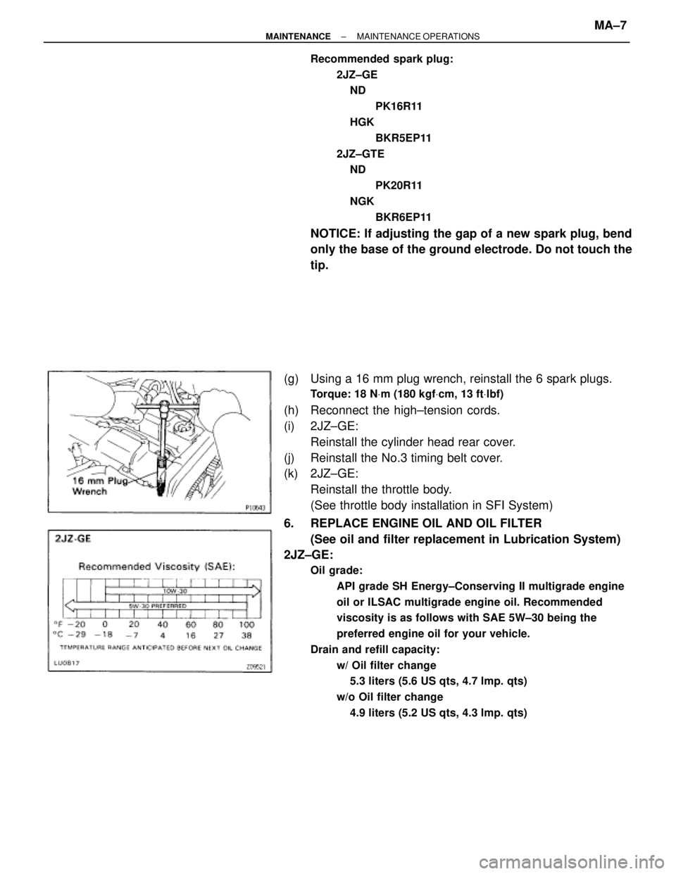
(g) Using a 16 mm plug wrench, reinstall the 6 spark plugs.
Torque: 18 NVm (180 kgfVcm, 13 ftVlbf)
(h) Reconnect the high±tension cords.
(i) 2JZ±GE:
Reinstall the cylinder head rear cover.
(j) Reinstall the No.3 timing belt cover.
(k) 2JZ±GE:
Reinstall the throttle body.
(See throttle body installation in SFI System)
6. REPLACE ENGINE OIL AND OIL FILTER
(See oil and filter replacement in Lubrication System)
2JZ±GE:
Oil grade:
API grade SH Energy±Conserving II multigrade engine
oil or ILSAC multigrade engine oil. Recommended
viscosity is as follows with SAE 5W±30 being the
preferred engine oil for your vehicle.
Drain and refill capacity:
w/ Oil filter change
5.3 liters (5.6 US qts, 4.7 lmp. qts)
w/o Oil filter change
4.9 liters (5.2 US qts, 4.3 lmp. qts)
± MAINTENANCEMAINTENANCE OPERATIONSMA±7