Page 17 of 2543
Warning for A/C compressor lock
If compressor lock occurs during air conditioning operation,
the [A/C] switch indicator on the air conditioning control as-
sembly starts blinking.
When this occurs, check for compressor lock using panel
diagnosis check then proceed to inspect the circuit or the
component.
Compressor lock sensor circuit " page AC±38
LIST OF OPERATION METHODS
By operating each of the air conditioning control switches as shown in the diagram below, it is possible to
enter the diagnosis check mode.
Indicator Check
Diagnostic
Sensor Check
(continuous operation)
Diagnostic
Sensor Check
(stepped operation)
Cancel check mode and can start
conditioning control
Actuator Check
(continuous
operation)
Turn ignition switch ON with AUTO and
switches held down.
If both Auto switch and switch are
not pressed at the same time.
: Indicates a switch operation
± AIR CONDITIONING SYSTEMTROUBLESHOOTINGAC±17
Page 18 of 2543
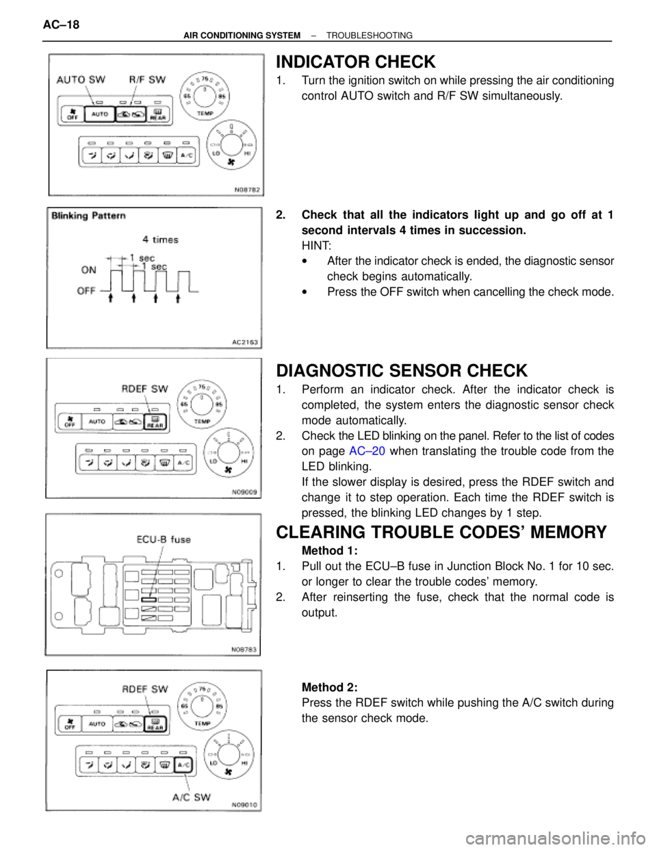
INDICATOR CHECK
1. Turn the ignition switch on while pressing the air conditioning
control AUTO switch and R/F SW simultaneously.
2. Check that all the indicators light up and go off at 1
second intervals 4 times in succession.
HINT:
wAfter the indicator check is ended, the diagnostic sensor
check begins automatically.
wPress the OFF switch when cancelling the check mode.
DIAGNOSTIC SENSOR CHECK
1. Perform an indicator check. After the indicator check is
completed, the system enters the diagnostic sensor check
mode automatically.
2. Check the LED blinking on the panel. Refer to the list of codes
on page AC±20 when translating the trouble code from the
LED blinking.
If the slower display is desired, press the RDEF switch and
change it to step operation. Each time the RDEF switch is
pressed, the blinking LED changes by 1 step.
CLEARING TROUBLE CODES' MEMORY
Method 1:
1. Pull out the ECU±B fuse in Junction Block No. 1 for 10 sec.
or longer to clear the trouble codes' memory.
2. After reinserting the fuse, check that the normal code is
output.
Method 2:
Press the RDEF switch while pushing the A/C switch during
the sensor check mode. AC±18
± AIR CONDITIONING SYSTEMTROUBLESHOOTING
Page 29 of 2543
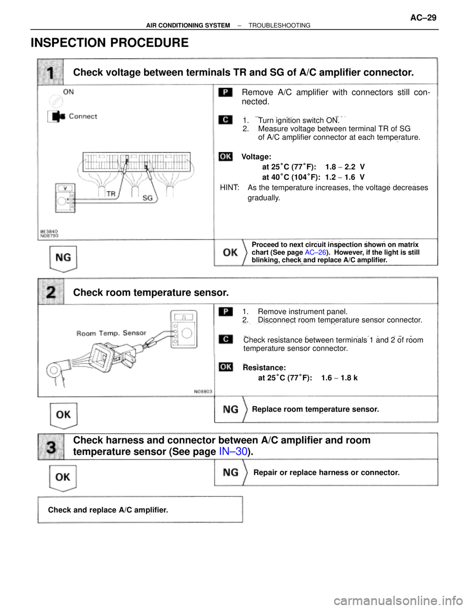
INSPECTION PROCEDURE
Proceed to next circuit inspection shown on matrix
chart (See page AC±26). However, if the light is still
blinking, check and replace A/C amplifier.
(See page IN±30).(See Page IN±30).
Remove A/C amplifier with connectors still con-
nected.
Check voltage between terminals TR and SG of A/C amplifier connector.
Check room temperature sensor.
Check harness and connector between A/C amplifier and room
temperature sensor (See page
IN±30).
Replace room temperature sensor.
Repair or replace harness or connector.
Check and replace A/C amplifier.
1. Turn ignition switch ON.
2. Measure voltage between terminal TR of SG
of A/C amplifier connector at each temperature.
1. Remove instrument panel.
2. Disconnect room temperature sensor connector.
Check resistance between terminals 1 and 2 of room
temperature sensor connector.
Resistance:
at 25°C (77°F): 1.6 ~ 1.8 k�
HINT: As the temperature increases, the voltage decreases
gradually.
Voltage:
at 25°C (77°F): 1.8 ~ 2.2 V
at 40°C (104°F): 1.2 ~ 1.6 V
± AIR CONDITIONING SYSTEMTROUBLESHOOTINGAC±29
Page 31 of 2543
(See page AC±26)
(See page IN±30).
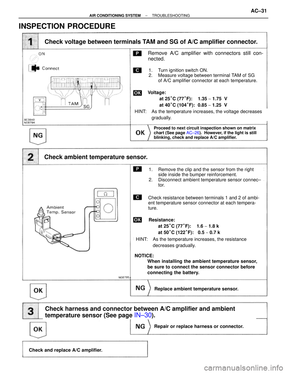
Check voltage between terminals TAM and SG of A/C amplifier connector.
Check ambient temperature sensor.
Check harness and connector between A/C amplifier and ambient
temperature sensor (See page
IN±30).
Proceed to next circuit inspection shown on matrix
chart (See page AC±26). However, if the light is still
blinking, check and replace A/C amplifier.
Check and replace A/C amplifier.
Repair or replace harness or connector.
Replace ambient temperature sensor.
Remove A/C amplifier with connectors still con-
nected.
1. Turn ignition switch ON.
2. Measure voltage between terminal TAM of SG
of A/C amplifier connector at each temperature.
HINT: As the temperature increases, the voltage decreases
gradually.
Voltage:
at 25°C (77°F): 1.35 ~ 1.75 V
at 40°C (104°F): 0.85 ~ 1.25 V
1. Remove the clip and the sensor from the right
side inside the bumper reinforcement.
2. Disconnect ambient temperature sensor connec±
tor.
Check resistance between terminals 1 and 2 of ambi-
ent temperature sensor connector at each tempera-
ture.
Resistance:
at 25°C (77°F): 1.6 ~ 1.8 k�
at 50°C (122°F): 0.5 ~ 0.7 k�
HINT: As the temperature increases, the resistance
decreases gradually.
NOTICE:
When installing the ambient temperature sensor,
be sure to connect the sensor connector before
connecting the battery.
INSPECTION PROCEDURE
± AIR CONDITIONING SYSTEMTROUBLESHOOTINGAC±31
Page 33 of 2543
INSPECTION PROCEDURE
(See page AC±26).
(See page IN±30)
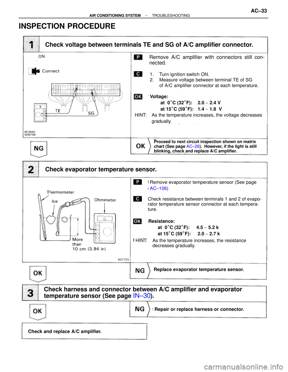
Check voltage between terminals TE and SG of A/C amplifier connector.
Check and replace A/C amplifier.
Repair or replace harness or connector.
Replace evaporator temperature sensor.
Check harness and connector between A/C amplifier and evaporator
temperature sensor (See page
IN±30).
Proceed to next circuit inspection shown on matrix
chart (See page AC±26). However, if the light is still
blinking, check and replace A/C amplifier.
Check evaporator temperature sensor.
Remove A/C amplifier with connectors still con-
nected.
1. Turn ignition switch ON.
2. Measure voltage between terminal TE of SG
of A/C amplifier connector at each temperature.
HINT: As the temperature increases, the voltage decreases
gradually.
Voltage:
at 0°C (32°F): 2.0 ~ 2.4 V
at 15°C (59°F): 1.4 ~ 1.8 V
Check resistance between terminals 1 and 2 of evapo-
rator temperature sensor connector at each tempera-
ture.
Resistance:
at 0°C (32°F): 4.5 ~ 5.2 k�
at 15°C (59°F): 2.0 ~ 2.7 k�
HINT: As the temperature increases, the resistance
decreases gradually.
Remove evaporator temperature sensor (See page
AC±106)
± AIR CONDITIONING SYSTEMTROUBLESHOOTINGAC±33
Page 35 of 2543
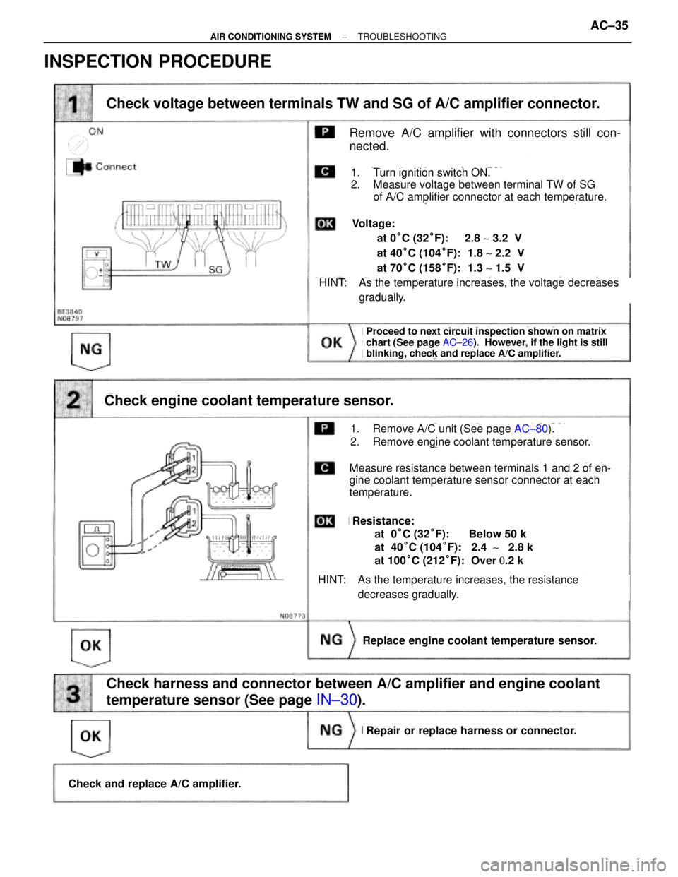
INSPECTION PROCEDURE
(See page AC±26).
(See page IN±30)
Check voltage between terminals TW and SG of A/C amplifier connector.
Proceed to next circuit inspection shown on matrix
chart (See page AC±26). However, if the light is still
blinking, check and replace A/C amplifier.
Check engine coolant temperature sensor.
Replace engine coolant temperature sensor.
Check harness and connector between A/C amplifier and engine coolant
temperature sensor (See page
IN±30).
Repair or replace harness or connector.
Check and replace A/C amplifier.
Remove A/C amplifier with connectors still con-
nected.
1. Turn ignition switch ON.
2. Measure voltage between terminal TW of SG
of A/C amplifier connector at each temperature.
HINT: As the temperature increases, the voltage decreases
gradually.
Voltage:
at 0°C (32°F): 2.8 ~ 3.2 V
at 40°C (104°F): 1.8 ~ 2.2 V
at 70°C (158°F): 1.3 ~ 1.5 V
1. Remove A/C unit (See page AC±80).
2. Remove engine coolant temperature sensor.
Measure resistance between terminals 1 and 2 of en-
gine coolant temperature sensor connector at each
temperature.
HINT: As the temperature increases, the resistance
decreases gradually.
Resistance:
at 0°C (32°F): Below 50 k�
at 40°C (104°F): 2.4 ~ 2.8 k�
at 100°C (212°F): Over 0.2 k�
± AIR CONDITIONING SYSTEMTROUBLESHOOTINGAC±35
Page 37 of 2543
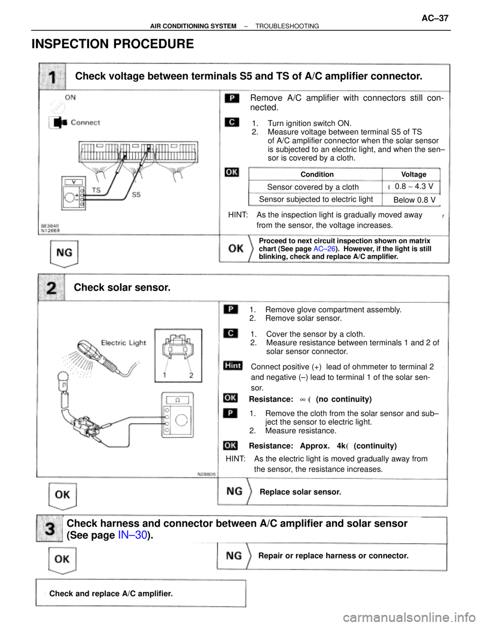
(See page IN±30)
Check and replace A/C amplifier.
Repair or replace harness or connector.
Check harness and connector between A/C amplifier and solar sensor
(See page
IN±30).
Replace solar sensor.
Check solar sensor.
Proceed to next circuit inspection shown on matrix
chart (See page AC±26). However, if the light is still
blinking, check and replace A/C amplifier.
Check voltage between terminals S5 and TS of A/C amplifier connector.
1. Turn ignition switch ON.
2. Measure voltage between terminal S5 of TS
of A/C amplifier connector when the solar sensor
is subjected to an electric light, and when the sen±
sor is covered by a cloth.
HINT: As the inspection light is gradually moved away
from the sensor, the voltage increases.
HINT: As the electric light is moved gradually away from
the sensor, the resistance increases.
1. Remove glove compartment assembly.
2. Remove solar sensor.
1. Cover the sensor by a cloth.
2. Measure resistance between terminals 1 and 2 of
solar sensor connector.
1. Remove the cloth from the solar sensor and sub±
ject the sensor to electric light.
2. Measure resistance.
Remove A/C amplifier with connectors still con-
nected.
ConditionVoltage
Sensor covered by a cloth
Sensor subjected to electric light
0.8 ~ 4.3 V
Below 0.8 V
Connect positive (+) lead of ohmmeter to terminal 2
and negative (±) lead to terminal 1 of the solar sen-
sor.
Resistance: 8 ��(no continuity)
Resistance: Approx. 4k��(continuity)
INSPECTION PROCEDURE
± AIR CONDITIONING SYSTEMTROUBLESHOOTINGAC±37
Page 41 of 2543
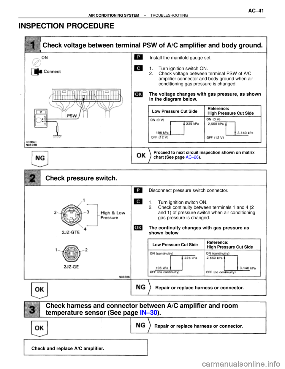
Check voltage between terminal PSW of A/C amplifier and body ground.
Check pressure switch.
Repair or replace harness or connector.
Check and replace A/C amplifier.
Repair or replace harness or connector.
Check harness and connector between A/C amplifier and room
temperature sensor (See page IN±30).
Proceed to next circuit inspection shown on matrix
chart (See page AC±26).
Install the manifold gauge set.
The voltage changes with gas pressure, as shown
in the diagram below.
1. Turn ignition switch ON.
2. Check voltage between terminal PSW of A/C
amplifier connector and body ground when air
conditioning gas pressure is changed.
Disconnect pressure switch connector.
1. Turn ignition switch ON.
2. Check continuity between terminals 1 and 4 (2
and 1) of pressure switch when air conditioning
gas pressure is changed.
The continuity changes with gas pressure as
shown below
Low Pressure Cut Side
Low Pressure Cut SideReference:
High Pressure Cut Side
Reference:
High Pressure Cut Side
INSPECTION PROCEDURE
± AIR CONDITIONING SYSTEMTROUBLESHOOTINGAC±41