Page 453 of 2543
INSPECTION PROCEDURE
Shift the shift lever to N position.
Jack up one of the rear wheels.
Connect the Check Harness A
(See page EG±404)
Disconnect power steering ECU connector
and cruise control ECU connector.
Turn ignition switch ON.
Measure voltage between terminal SP1 of ECM
connector and body ground when the wheel is
turned slowly.
Check voltage between terminal SP1 of ECM connector and body ground.
Voltage is generated intermittently.
Check and replace ECM.
Repair or replace harness or connector be-
tween ECM and telltale light RH.
Check operation of odometer and trip meter (telltale light RH (See page
BR±48))
AT1±67± AT340E (2JZ±GE) AUTOMATIC TRANSMISSIONTROUBLESHOOTING
Page 464 of 2543
INSPECTION PROCEDURE
(See page EG±219).
Turn ignition switch ON.
Do not depress the brake pedal during this test.
The voltage will stay at 0 V if depressed.
Voltage changes from 0 V to 8 V by stages.
Check throttle position signal.
Check voltage at the terminal TT of the DLC2
while gradually depressing the accelerator pedal
from the fully closed position to the fully opened
position.
Proceed to next circuit inspection shown on
matrix chart (See page AT1±58).
Replace throttle position sensor.
Repair or replace harness or connector.
Check and replace ECM.
Check harness and connector between ECM and throttle position sen-
sor (See page IN±30).
AT1±78± AT340E (2JZ±GE) AUTOMATIC TRANSMISSIONTROUBLESHOOTING
Page 466 of 2543
Connect the Check Harness A to the ECM
(See page EG±404).
Turn ignition switch ON.
Check voltage between terminal KD of ECM connector and body ground.
Measure voltage between terminal KD of ECM
connector and body ground when accel. pedal is
fully depressed or not.
Proceed to next circuit inspection shown on
matrix chart (See page AT1±58).
Released
(Kick±down SW is OFF)
Fully depressed
(Kick±down SW is ON)
Accel. pedalVoltage
9 ± 14 V
Below 3 V
Check kick±down switch.
Disconnect kick±down switch connector (See
page AT1±15).
Measure voltage between terminals 1 and 2 of
kick±down switch connector when kick±down
switch is on and off.
Kick±down switch
ON
OFF
Resistance
C � (continuity)
8 � (open)
Replace kick±down switch.
Check harness and connector between ECM and kick±down switch, kick±
down switch and body ground (See page IN±30).
Repair or replace harness connector.
Check and replace ECM.
INSPECTION PROCEDURE
AT1±80± AT340E (2JZ±GE) AUTOMATIC TRANSMISSIONTROUBLESHOOTING
Page 468 of 2543
Connect the Check Harness A to the ECM
(See page EG±404).
Turn ignition switch ON.
Check voltage between terminals NSW, 2, L of ECM connector and body
ground.
Measure voltage between terminals NSW, 2, L of
ECM connector and body ground when the shift
lever is positioned to the following positions.
Proceed to next circuit inspection shown on
matrix chart (See page AT1±58).
Check park/neutral position switch.
Jack up the vehicle.
Remove park/neutral position switch (See
page AT1±15).
Replace park/neutral position switch.
Check harness and connector between battery and park/neutral position
switch, park/neutral position switch and ECM (See page IN±30).
Repair or replace harness and connector.
Check and replace ECM.
Check continuity between each terminal shown
below when the shift lever is positioned to each
position.
The voltage will drop slighty due to lighting up of the
back up light.
INSPECTION PROCEDURE
AT1±82± AT340E (2JZ±GE) AUTOMATIC TRANSMISSIONTROUBLESHOOTING
Page 470 of 2543
Connect a voltmeter to the terminals TT and
E1 of the DLC2.
Turn ignition switch ON (Do not start the en-
gine).
Fully depress the accelerator pedal until the
voltmeter indicates 8 V and hold it.
Depress and release the brake pedal and
check the voltage.
Check stop light signal.
Brake pedal
Proceed to next circuit inspection shown on
matrix chart (See page AT1±58).
Check harness and connector between ECM and stop light switch
(See page IN±30).
Repair or replace harness or connector
Voltage
Depressed0 V
Released8 V
Check and replace ECM. AT1±84
± AT340E (2JZ±GE) AUTOMATIC TRANSMISSIONTROUBLESHOOTING
Page 472 of 2543

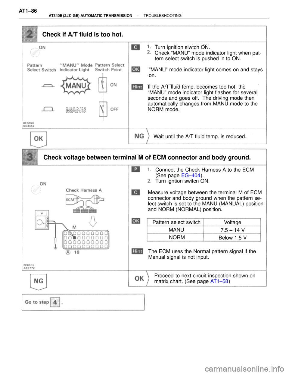
Turn ignition siwtch ON.
Check ªMANUº mode indicator light when pat-
tern select switch is pushed in to ON.
Check if A/T fluid is too hot.
Pattern select switch
Connect the Check Harness A to the ECM
(See page EG±404).
Turn igntion switcn ON.
Check voltage between terminal M of ECM connector and body ground.
Proceed to next circuit inspection shown on
matrix chart. (See page AT1±58)
Voltage
MANU7.5 ± 14 V
NORMBelow 1.5 V
Wait until the A/T fluid temp. is reduced.
The ECM uses the Normal pattern signal if the
Manual signal is not input.
Measure voltage between the terminal M of ECM
connector and body ground when the pattern se-
lect switch is set to the MANU (MANUAL) position
and NORM (NORMAL) position.
ºMANUº mode indicator light comes on and stays
on.
If the A/T fluid temp. becomes too hot, the
ªMANUº mode indicator light flashes for several
seconds and goes off. The driving mode then
automatically changes from MANU mode to the
NORM mode. AT1±86
± AT340E (2JZ±GE) AUTOMATIC TRANSMISSIONTROUBLESHOOTING
Page 475 of 2543

INSPECTION PROCEDURE
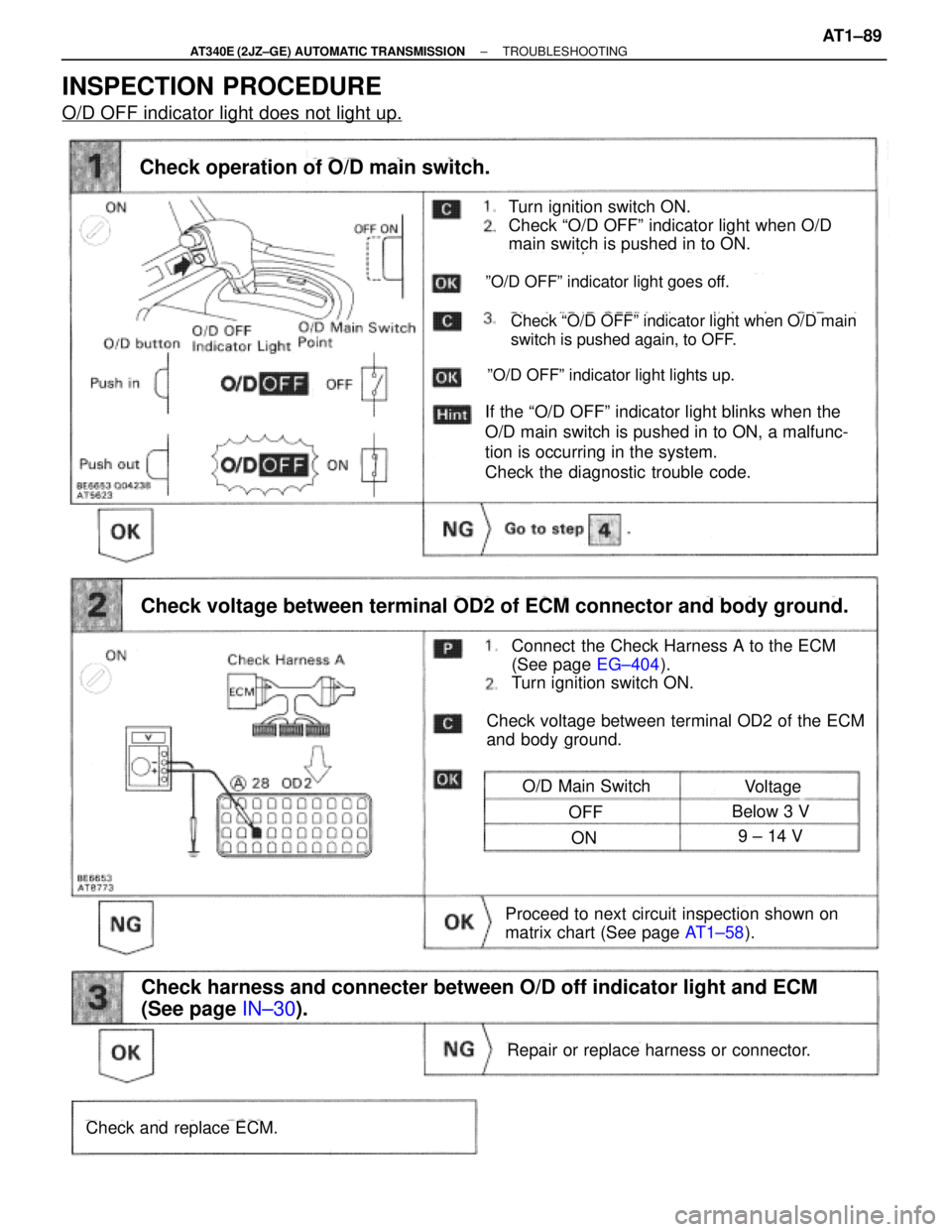
O/D OFF indicator light does not light up.
Turn ignition switch ON.
Check ªO/D OFFº indicator light when O/D
main switch is pushed in to ON.
Check operation of O/D main switch.
Connect the Check Harness A to the ECM
(See page EG±404).
Turn ignition switch ON.
ºO/D OFFº indicator light goes off.
If the ªO/D OFFº indicator light blinks when the
O/D main switch is pushed in to ON, a malfunc-
tion is occurring in the system.
Check the diagnostic trouble code.
Check voltage between terminal OD2 of ECM connector and body ground.
ºO/D OFFº indicator light lights up.
Check ªO/D OFFº indicator light when O/D main
switch is pushed again, to OFF.
Check voltage between terminal OD2 of the ECM
and body ground.
O/D Main SwitchVoltage
OFFBelow 3 V
ON9 ± 14 V
Proceed to next circuit inspection shown on
matrix chart (See page AT1±58).
Repair or replace harness or connector.
Check and replace ECM.
Check harness and connecter between O/D off indicator light and ECM
(See page IN±30).
± AT340E (2JZ±GE) AUTOMATIC TRANSMISSIONTROUBLESHOOTINGAT1±89
Page 477 of 2543
O D Cancel Signal Circuit
CIRCUIT DESCRIPTION
While driving with cruise control activated, in order to minimize gear shifting and provide smooth uphill cruising,
overdrive may be prohibited temporarily in some conditions.
The Cruise Control ECU sends O/D cut signals to the ECM as necessary and the ECM cancels overdrive shifting
until these signals are discontinued.
(For details, see the cruise control section, page BE±162)
WIRING DIAGRAM
INSPECTION PROCEDURE
Connect the Check Harness A to the ECM
(See page EG±404).
Turn ignition switch ON.
Check and replace ECM.
Check voltage between terminal OD1 of ECM connector and body ground.
Measure voltage between terminal OD1 of ECM
connector and body ground.
Proceed to next circuit inspection shown on
matrix chart (See page AT1±58).
Voltage: 4 ± 6 V
± AT340E (2JZ±GE) AUTOMATIC TRANSMISSIONTROUBLESHOOTINGAT1±91