Page 43 of 2543

(See page IN±30).
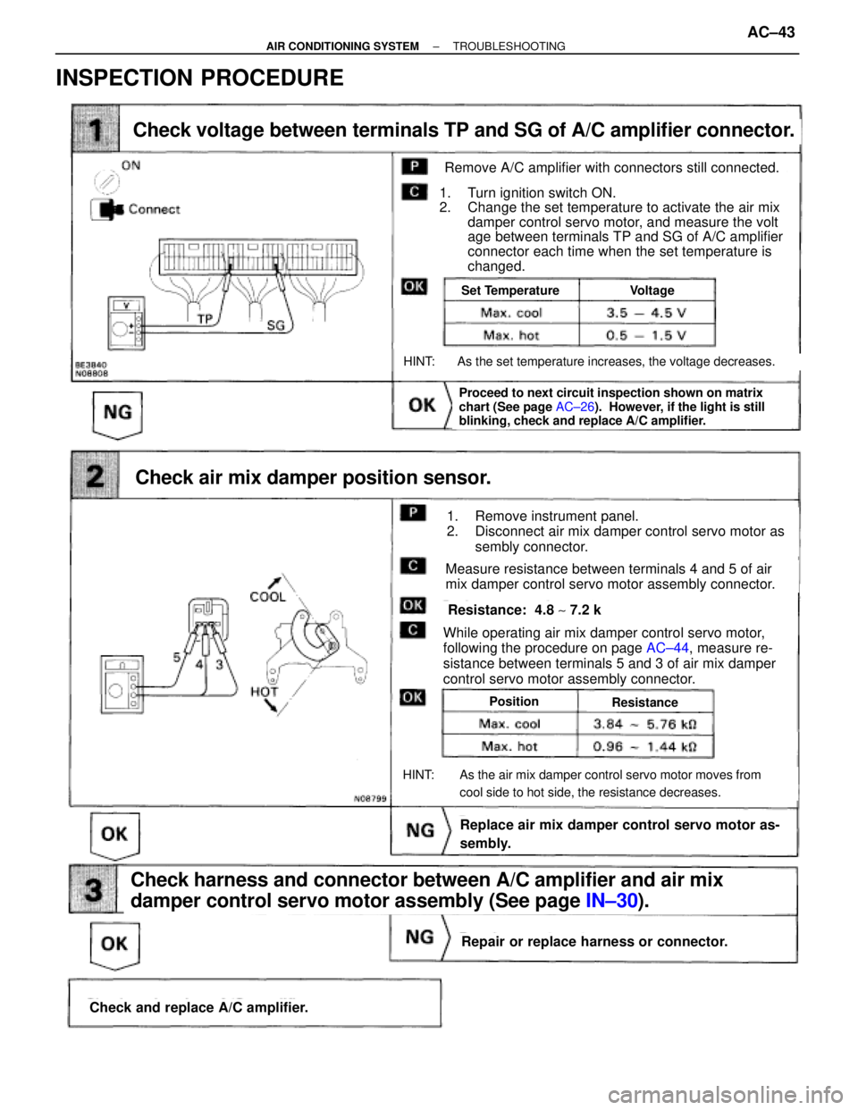
Check voltage between terminals TP and SG of A/C amplifier connector.
Check air mix damper position sensor.
Check and replace A/C amplifier.
Check harness and connector between A/C amplifier and air mix
damper control servo motor assembly (See page IN±30).
Repair or replace harness or connector.
Replace air mix damper control servo motor as-
sembly.
Proceed to next circuit inspection shown on matrix
chart (See page AC±26). However, if the light is still
blinking, check and replace A/C amplifier.
Set TemperatureVoltage
PositionResistance
Remove A/C amplifier with connectors still connected.
1. Turn ignition switch ON.
2. Change the set temperature to activate the air mix
damper control servo motor, and measure the volt
age between terminals TP and SG of A/C amplifier
connector each time when the set temperature is
changed.
HINT: As the set temperature increases, the voltage decreases.
1. Remove instrument panel.
2. Disconnect air mix damper control servo motor as
sembly connector.
Measure resistance between terminals 4 and 5 of air
mix damper control servo motor assembly connector.
While operating air mix damper control servo motor,
following the procedure on page AC±44, measure re-
sistance between terminals 5 and 3 of air mix damper
control servo motor assembly connector.
HINT: As the air mix damper control servo motor moves from
cool side to hot side, the resistance decreases.
Resistance: 4.8 ~ 7.2 k�
INSPECTION PROCEDURE
± AIR CONDITIONING SYSTEMTROUBLESHOOTINGAC±43
Page 49 of 2543

(See page IN±30).
AC±50,
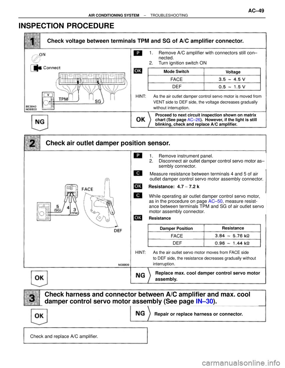
Check voltage between terminals TPM and SG of A/C amplifier connector.
Check and replace A/C amplifier.
Repair or replace harness or connector.
Check harness and connector between A/C amplifier and max. cool
damper control servo motor assembly (See page IN±30).
Replace max. cool damper control servo motor
assembly.
Check air outlet damper position sensor.
Proceed to next circuit inspection shown on matrix
chart (See page AC±26). However, if the light is still
blinking, check and replace A/C amplifier.
ResistanceDamper Position
Resistance: 4.7 ~ 7.2 k�
While operating air outlet damper control servo motor,
as in the procedure on page AC±50, measure resist-
ance between terminals TPM and SG of air outlet servo
motor assembly connector.
Resistance
HINT: As the air outlet servo motor moves from FACE side
to DEF side, the resistance decreases gradually without
interruption.
Measure resistance between terminals 4 and 5 of air
outlet damper control servo motor assembly connector.
1. Remove instrument panel.
2. Disconnect air outlet damper control servo motor as±
sembly connector.
HINT: As the air outlet damper control servo motor is moved from
VENT side to DEF side, the voltage decreases gradually
without interruption.
Mode SwitchVoltage
1. Remove A/C amplifier with connectors still con±
nected.
2. Turn ignition switch ON
FACE
FACE
DEF
DEF
INSPECTION PROCEDURE
± AIR CONDITIONING SYSTEMTROUBLESHOOTINGAC±49
Page 52 of 2543
Back Up Power Source Circuit
CIRCUIT DESCRIPTION
This is the back up power source for the A/C amplifier. Power is supplied even when the ignition switch is off
and is used for diagnostic sensor check memory, etc.
AC±52± AIR CONDITIONING SYSTEMTROUBLESHOOTING
Page 54 of 2543
IG Power Source Circuit
CIRCUIT DESCRIPTION
This is the power source for the A/C amplifier and servo motors, etc.
INSPECTION PROCEDURE
Remove the A/C amplifier with connector still con-
nected
Voltage: Battery positive voltage
1. Turn ignition switch ON.
2. Measure voltage between terminals IG and GND
of A/C amplifier.
Proceed to next circuit inspection shown on matrix
chart (See page AC±26).
Go to step
Check voltage between terminals IG and GND of A/C amplifier connector.
AC±54± AIR CONDITIONING SYSTEMTROUBLESHOOTING
Page 57 of 2543
INSPECTION PROCEDURE
Check voltage between terminal ACC of A/C amplifier connector and
body ground.
Remove the A/C amplifier with connector still connected
Voltage: Battery positive voltage
1. Turn ignition switch To ACC.
2. Measure voltage between terminals ACC of A/C
amplifier connector and body ground.
Remove CIG fuse from J/B No. 1.
Check continuity of CIG fuse.
Continuity
Proceed to next circuit inspection shown on matrix
chart (See page AC±26).
Check CIG fuse.
Check for short in all the harness and compo-
nents to the CIG fuse (See attached wiring
diagram).
Check and repair harness and connector between
A/C amplifier and battery.
± AIR CONDITIONING SYSTEMTROUBLESHOOTINGAC±57
Page 59 of 2543

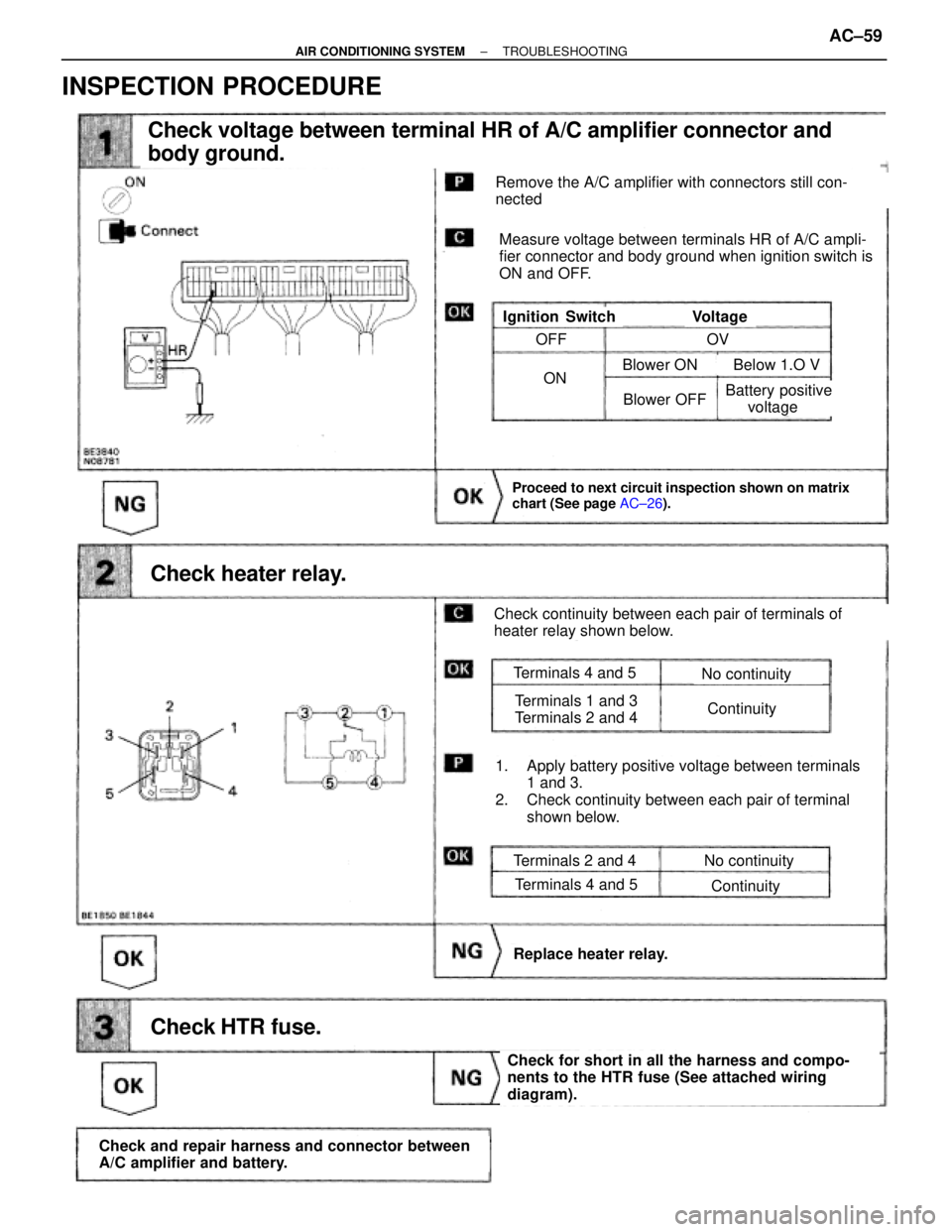
Check voltage between terminal HR of A/C amplifier connector and
body ground.
Check heater relay.
Proceed to next circuit inspection shown on matrix
chart (See page AC±26).
Check HTR fuse.
Check and repair harness and connector between
A/C amplifier and battery.
Check for short in all the harness and compo-
nents to the HTR fuse (See attached wiring
diagram).
Replace heater relay.
Remove the A/C amplifier with connectors still con-
nected
Measure voltage between terminals HR of A/C ampli-
fier connector and body ground when ignition switch is
ON and OFF.
VoltageIgnition Switch
Check continuity between each pair of terminals of
heater relay shown below.
1. Apply battery positive voltage between terminals
1 and 3.
2. Check continuity between each pair of terminal
shown below.
Terminals 2 and 4
Terminals 4 and 5
No continuity
Continuity
Terminals 4 and 5
Terminals 1 and 3
Terminals 2 and 4
No continuity
Continuity
OFF
ON
OV
Blower OFF
Blower ON Below 1.O V
Battery positive
voltage
INSPECTION PROCEDURE
± AIR CONDITIONING SYSTEMTROUBLESHOOTINGAC±59
Page 60 of 2543
Blower Motor Circuit
CIRCUIT DESCRIPTION
This is the power source for the blower motor.
INSPECTION PROCEDURE
Check voltage between terminal BLW of A/C amplifier connector and
body ground.
Proceed to next circuit inspection shown on matrix
chart (See page AC±26).
Go to step
Remove the A/C amplifier with connector still con-
nected
Voltage: 1 ± 3 V
1. Turn ignition switch To ON.
2. Operate blower motor.
3. Measure voltage between terminals BLW of A/C
amplifier connector and body ground.
AC±60± AIR CONDITIONING SYSTEMTROUBLESHOOTING
Page 61 of 2543
(See page AC±99).
Check blower motor.
Go to step
Replace blower motor.
Check blower motor control relay.
Replace blower motor control relay.
Repair or replace harness or connector
Remove blower motor control relay with connectors
still connected
1. Turn ignition switch To ON.
2. Operate blower motor.
TerminalsStandard Value
Continuity
Battery Positive
Voltage
Battery Positive
Voltage
Battery Positive
Voltage
Connect positive (+) lead to terminal 2
of blower motor connector, negative (±) lead to
terminal 1.
Remove blower motor control (see page AC±99).
Blower motor operates smoothly.
± AIR CONDITIONING SYSTEMTROUBLESHOOTINGAC±61