1995 TOYOTA SUPRA oil dipstick
[x] Cancel search: oil dipstickPage 428 of 2543
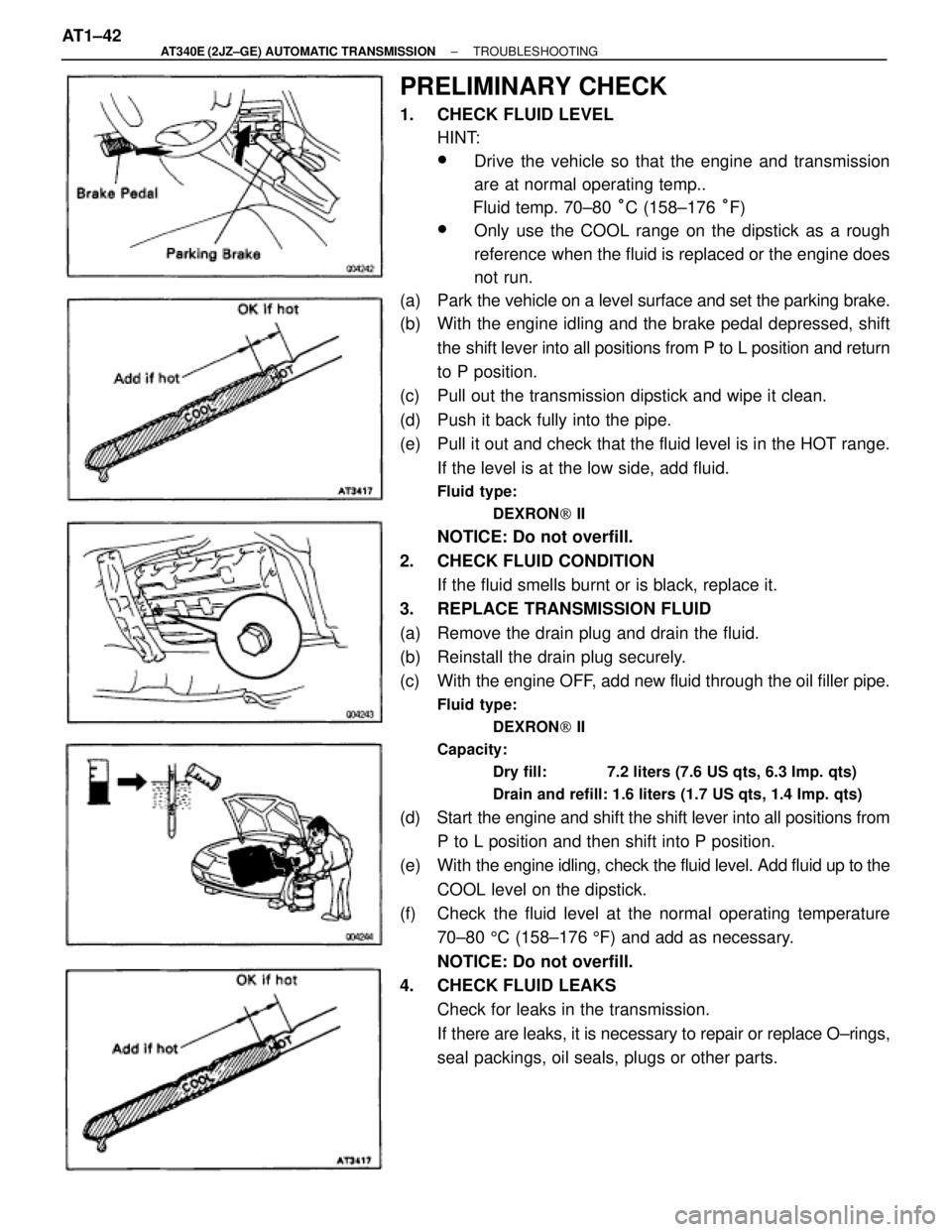
PRELIMINARY CHECK
1. CHECK FLUID LEVEL
HINT:
wDrive the vehicle so that the engine and transmission
are at normal operating temp..
Fluid temp. 70±80 °C (158±176 °F)
wOnly use the COOL range on the dipstick as a rough
reference when the fluid is replaced or the engine does
not run.
(a) Park the vehicle on a level surface and set the parking brake.
(b) With the engine idling and the brake pedal depressed, shift
the shift lever into all positions from P to L position and return
to P position.
(c) Pull out the transmission dipstick and wipe it clean.
(d) Push it back fully into the pipe.
(e) Pull it out and check that the fluid level is in the HOT range.
If the level is at the low side, add fluid.
Fluid type:
DEXRON[ II
NOTICE: Do not overfill.
2. CHECK FLUID CONDITION
If the fluid smells burnt or is black, replace it.
3. REPLACE TRANSMISSION FLUID
(a) Remove the drain plug and drain the fluid.
(b) Reinstall the drain plug securely.
(c) With the engine OFF, add new fluid through the oil filler pipe.
Fluid type:
DEXRON[ II
Capacity:
Dry fill: 7.2 liters (7.6 US qts, 6.3 Imp. qts)
Drain and refill: 1.6 liters (1.7 US qts, 1.4 Imp. qts)
(d) Start the engine and shift the shift lever into all positions from
P to L position and then shift into P position.
(e) With the engine idling, check the fluid level. Add fluid up to the
COOL level on the dipstick.
(f) Check the fluid level at the normal operating temperature
70±80 5C (158±176 5F) and add as necessary.
NOTICE: Do not overfill.
4. CHECK FLUID LEAKS
Check for leaks in the transmission.
If there are leaks, it is necessary to repair or replace O±rings,
seal packings, oil seals, plugs or other parts. AT1±42
± AT340E (2JZ±GE) AUTOMATIC TRANSMISSIONTROUBLESHOOTING
Page 526 of 2543
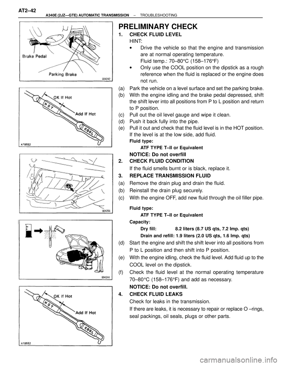
PRELIMINARY CHECK
1. CHECK FLUID LEVEL
HINT:
wDrive the vehicle so that the engine and transmission
are at normal operating temperature.
Fluid temp.: 70±805C (158±1765F)
wOnly use the COOL position on the dipstick as a rough
reference when the fluid is replaced or the engine does
not run.
(a) Park the vehicle on a level surface and set the parking brake.
(b) With the engine idling and the brake pedal depressed, shift
the shift lever into all positions from P to L position and return
to P position.
(c) Pull out the oil level gauge and wipe it clean.
(d) Push it back fully into the pipe.
(e) Pull it out and check that the fluid level is in the HOT position.
If the level is at the low side, add fluid.
Fluid type:
ATF TYPE T±II or Equivalent
NOTICE: Do not overfill
2. CHECK FLUID CONDITION
If the fluid smells burnt or is black, replace it.
3. REPLACE TRANSMISSION FLUID
(a) Remove the drain plug and drain the fluid.
(b) Reinstall the drain plug securely.
(c) With the engine OFF, add new fluid through the oil filler pipe.
Fluid type:
ATF TYPE T±II or Equivalent
Capacity:
Dry fill: 8.2 liters (8.7 US qts, 7.2 Imp. qts)
Drain and refill: 1.9 liters (2.0 US qts, 1.6 Imp. qts)
(d) Start the engine and shift the shift lever into all positions from
P to L position and then shift into P position.
(e) With the engine idling, check the fluid level. Add fluid up to the
COOL level on the dipstick.
(f) Check the fluid level at the normal operating temperature
70±805C (158±1765F) and add as necessary.
NOTICE: Do not overfill.
4. CHECK FLUID LEAKS
Check for leaks in the transmission.
If there are leaks, it is necessary to repair or replace O ±rings,
seal packings, oil seals, plugs or other parts. AT2±42
± A340E (2JZÐGTE) AUTOMATIC TRANSMISSIONTROUBLESHOOTING
Page 1213 of 2543
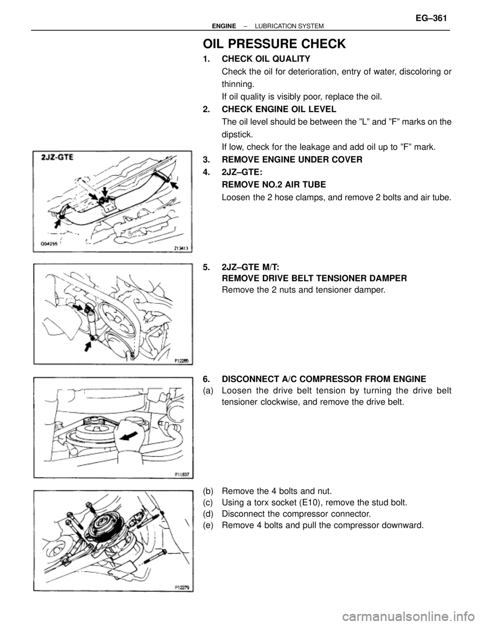
OIL PRESSURE CHECK
1. CHECK OIL QUALITY
Check the oil for deterioration, entry of water, discoloring or
thinning.
If oil quality is visibly poor, replace the oil.
2. CHECK ENGINE OIL LEVEL
The oil level should be between the ºLº and ºFº marks on the
dipstick.
If low, check for the leakage and add oil up to ºFº mark.
3. REMOVE ENGINE UNDER COVER
4. 2JZ±GTE:
REMOVE NO.2 AIR TUBE
Loosen the 2 hose clamps, and remove 2 bolts and air tube.
5. 2JZ±GTE M/T:
REMOVE DRIVE BELT TENSIONER DAMPER
Remove the 2 nuts and tensioner damper.
6. DISCONNECT A/C COMPRESSOR FROM ENGINE
(a) Loosen the drive belt tension by turning the drive belt
tensioner clockwise, and remove the drive belt.
(b) Remove the 4 bolts and nut.
(c) Using a torx socket (E10), remove the stud bolt.
(d) Disconnect the compressor connector.
(e) Remove 4 bolts and pull the compressor downward.
± ENGINELUBRICATION SYSTEMEG±361
Page 1219 of 2543
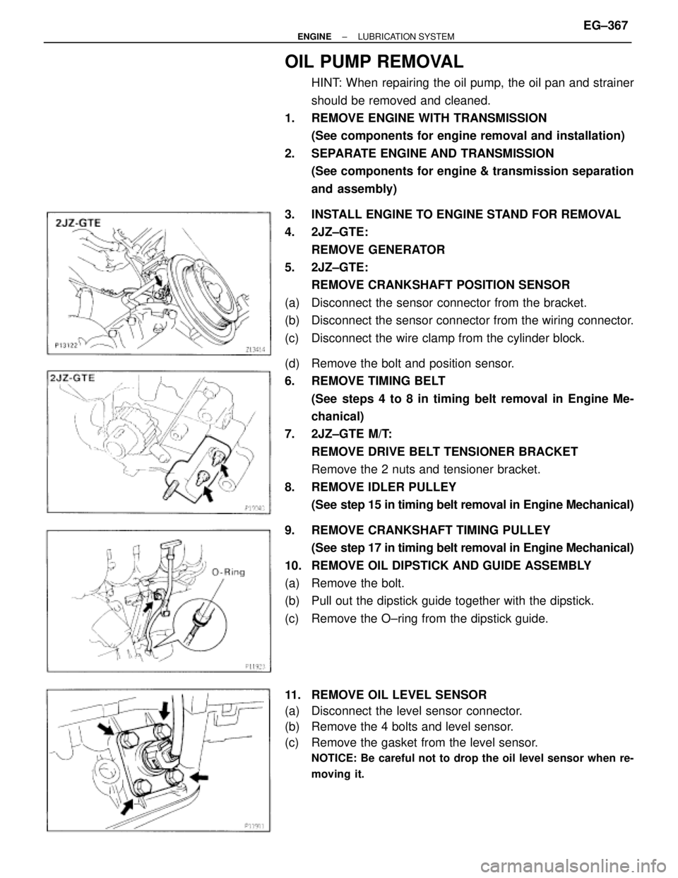
OIL PUMP REMOVAL
HINT: When repairing the oil pump, the oil pan and strainer
should be removed and cleaned.
1. REMOVE ENGINE WITH TRANSMISSION
(See components for engine removal and installation)
2. SEPARATE ENGINE AND TRANSMISSION
(See components for engine & transmission separation
and assembly)
3. INSTALL ENGINE TO ENGINE STAND FOR REMOVAL
4. 2JZ±GTE:
REMOVE GENERATOR
5. 2JZ±GTE:
REMOVE CRANKSHAFT POSITION SENSOR
(a) Disconnect the sensor connector from the bracket.
(b) Disconnect the sensor connector from the wiring connector.
(c) Disconnect the wire clamp from the cylinder block.
(d) Remove the bolt and position sensor.
6. REMOVE TIMING BELT
(See steps 4 to 8 in timing belt removal in Engine Me-
chanical)
7. 2JZ±GTE M/T:
REMOVE DRIVE BELT TENSIONER BRACKET
Remove the 2 nuts and tensioner bracket.
8. REMOVE IDLER PULLEY
(See step 15 in timing belt removal in Engine Mechanical)
9. REMOVE CRANKSHAFT TIMING PULLEY
(See step 17 in timing belt removal in Engine Mechanical)
10. REMOVE OIL DIPSTICK AND GUIDE ASSEMBLY
(a) Remove the bolt.
(b) Pull out the dipstick guide together with the dipstick.
(c) Remove the O±ring from the dipstick guide.
11. REMOVE OIL LEVEL SENSOR
(a) Disconnect the level sensor connector.
(b) Remove the 4 bolts and level sensor.
(c) Remove the gasket from the level sensor.
NOTICE: Be careful not to drop the oil level sensor when re-
moving it.
± ENGINELUBRICATION SYSTEMEG±367
Page 1227 of 2543
6. INSTALL OIL STRAINER
Install a new gasket and the oil strainer with the bolt and 2
nuts.
Torque: 8.8 NVm (90 kgfVcm, 78 in.Vlbf)
7. INSTALL NO.2 OIL PAN
(a) Remove any old packing (FIPG) material and be careful not
to drop any oil on the contact surfaces of the No.1 and No.2
oil pans.
wUsing a razor blade and gasket scraper, remove all the
old packing (FIPG) material from the gasket surfaces
and sealing groove.
wThoroughly clean all components to remove all the
debris.
wUsing a non±residue solvent, clean both sealing
surfaces.
NOTICE: Do not use a solvent which will affect the painted sur-
faces.
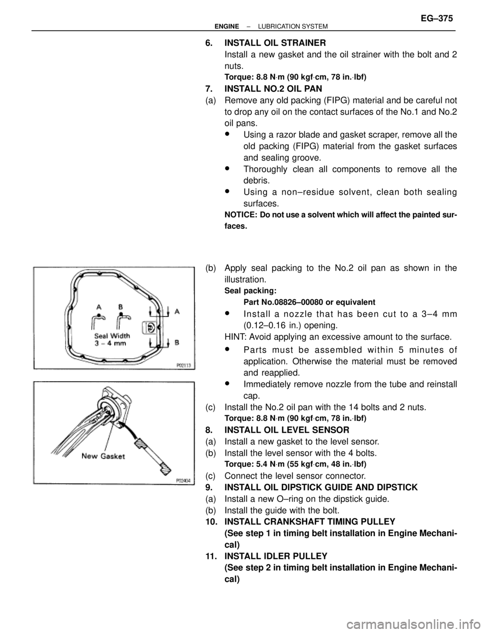
(b) Apply seal packing to the No.2 oil pan as shown in the
illustration.
Seal packing:
Part No.08826±00080 or equivalent
wInstall a nozzle that has been cut to a 3±4 mm
(0.12±0.16 in.) opening.
HINT: Avoid applying an excessive amount to the surface.
wParts must be assembled within 5 minutes of
application. Otherwise the material must be removed
and reapplied.
wImmediately remove nozzle from the tube and reinstall
cap.
(c) Install the No.2 oil pan with the 14 bolts and 2 nuts.
Torque: 8.8 NVm (90 kgfVcm, 78 in.Vlbf)
8. INSTALL OIL LEVEL SENSOR
(a) Install a new gasket to the level sensor.
(b) Install the level sensor with the 4 bolts.
Torque: 5.4 NVm (55 kgfVcm, 48 in.Vlbf)
(c) Connect the level sensor connector.
9. INSTALL OIL DIPSTICK GUIDE AND DIPSTICK
(a) Install a new O±ring on the dipstick guide.
(b) Install the guide with the bolt.
10. INSTALL CRANKSHAFT TIMING PULLEY
(See step 1 in timing belt installation in Engine Mechani-
cal)
11. INSTALL IDLER PULLEY
(See step 2 in timing belt installation in Engine Mechani-
cal)
± ENGINELUBRICATION SYSTEMEG±375
Page 1247 of 2543
21. REPLACE TRANSMISSION OIL (FLUID) AND
DIFFERENTIAL OIL
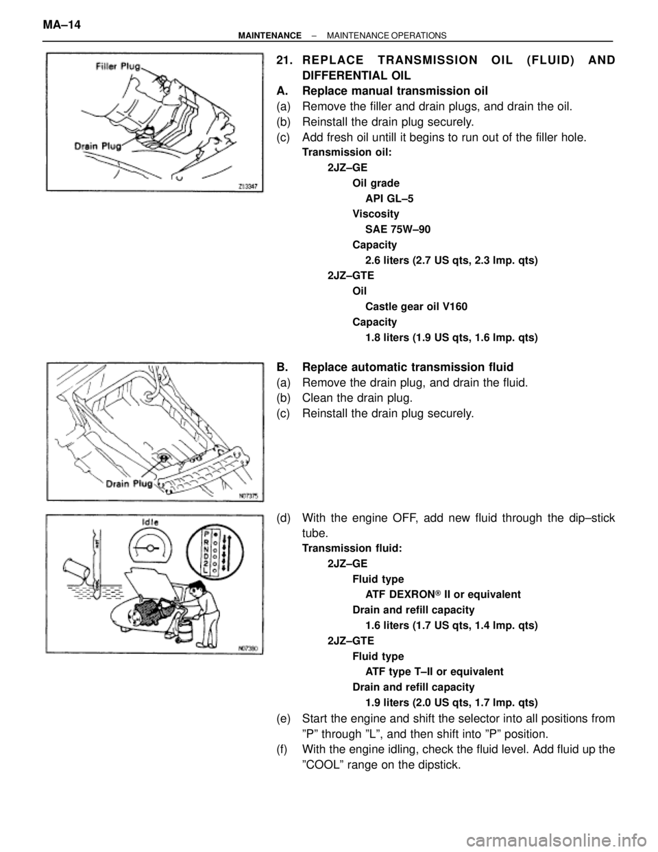
A. Replace manual transmission oil
(a) Remove the filler and drain plugs, and drain the oil.
(b) Reinstall the drain plug securely.
(c) Add fresh oil untill it begins to run out of the filler hole.
Transmission oil:
2JZ±GE
Oil grade
API GL±5
Viscosity
SAE 75W±90
Capacity
2.6 liters (2.7 US qts, 2.3 lmp. qts)
2JZ±GTE
Oil
Castle gear oil V160
Capacity
1.8 liters (1.9 US qts, 1.6 lmp. qts)
B. Replace automatic transmission fluid
(a) Remove the drain plug, and drain the fluid.
(b) Clean the drain plug.
(c) Reinstall the drain plug securely.
(d) With the engine OFF, add new fluid through the dip±stick
tube.
Transmission fluid:
2JZ±GE
Fluid type
ATF DEXRON® II or equivalent
Drain and refill capacity
1.6 liters (1.7 US qts, 1.4 lmp. qts)
2JZ±GTE
Fluid type
ATF type T±II or equivalent
Drain and refill capacity
1.9 liters (2.0 US qts, 1.7 lmp. qts)
(e) Start the engine and shift the selector into all positions from
ºPº through ºLº, and then shift into ºPº position.
(f) With the engine idling, check the fluid level. Add fluid up the
ºCOOLº range on the dipstick. MA±14
± MAINTENANCEMAINTENANCE OPERATIONS
Page 1251 of 2543

18. BRAKE PEDAL
(a) Check that pedal for smooth operation.
(b) Check that the pedal has the proper reserve
distance and freeplay.
(c) Check the brake booster function.
19. BRAKES
At a safe place, check that the brakes do not
pull to one side when applied.
20. PARKING BRAKE
(a) Check that the pedal has the proper travel.
(b) On a safe incline, check that the vehicle is
held securely with only the parking brake
applied.
21. AUTOMATIC TRANSMISSION PARK
MECHANISM
(a) Check the lock release button of the selector
lever for proper and smooth operation.
(b) On a safe incline, check that the vehicle is
held securely with the selector lever in the ºPº
position and all brakes released.
UNDER HOOD
22. WINDSHIELD WASHER FLUID
Check that there is sufficient fluid in the tank.
23. ENGINE COOLANT LEVEL
Check that the coolant level is between the
LEVEL lines on the see±through reservoir at
normal temperature (20°C (68°F)).
24. RADIATOR AND HOSES
(a) Check that the front of the radiator is clean
and not blocked with leaves, dirt or bugs.
(b) Check the hoses for cracks, kinks, rot or
loose connections.
25. BATTERY ELECTROLYTE LEVEL
Check the indicator.
When the indicator color is blue, the condition
is satisfactory. A red color indicates that dis-
tilled water must be added, and white indi-
cates that charging is necessary.
26. BRAKE FLUID LEVEL
Check that the brake fluid level is near the up-
per level line on the see±through reservoir.27. ENGINE DRIVE BELT
Check drive belt for fraying, cracks, wear or
oil contamination.
28. ENGINE OIL LEVEL
Check that level on the dipstick with the en-
gine turned off.
29. POWER STEERING FLUID LEVEL
Check the level on the dipstick.
The level should be in the ºHOTº or ºCOLDº
range depending on the fluid temperature.
30. A U TO M AT I C TRANSMISSION FLUID
LEVEL
(a) Park the vehicle on a level surface.
(b) With the engine idling and the parking and
foot brake applied, shift the selector into all
positions from ºPº to ºLº, and then shift into ºPº
position.
(c) Turn and pull out the dipstick and wipe off the
fluid with a clean rag.
Re±insert the dipstick fully and check that the
fluid level is in the ºHOTº range.
(d) Perform this check with the fluid at normal
driving temperature (70±80°C (158±176°F)).
If the level is at the low side, add fluid.
NOTICE: Do not overfill.
HINT: Wait about 30 minutes before checking
the fluid level after extended driving at high
speeds in hot weather, driving in heavy traffic
or with a trailer.
31. EXHAUST SYSTEM
Visually inspect for cracks, holes or loose
supports.
If any change in the sound of the exhaust or
smell of the exhaust fumes is noticed, have
the cause located and correted. MA±18
± MAINTENANCEGENERAL MAINTENANCE
Page 1356 of 2543
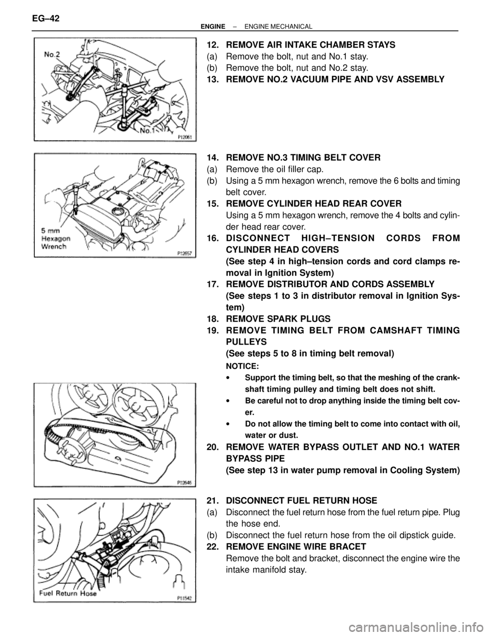
12. REMOVE AIR INTAKE CHAMBER STAYS
(a) Remove the bolt, nut and No.1 stay.
(b) Remove the bolt, nut and No.2 stay.
13. REMOVE NO.2 VACUUM PIPE AND VSV ASSEMBLY
14. REMOVE NO.3 TIMING BELT COVER
(a) Remove the oil filler cap.
(b) Using a 5 mm hexagon wrench, remove the 6 bolts and timing
belt cover.
15. REMOVE CYLINDER HEAD REAR COVER
Using a 5 mm hexagon wrench, remove the 4 bolts and cylin-
der head rear cover.
16. D I S C O N N E C T H I G H ± T E N S I O N C O R D S F R O M
CYLINDER HEAD COVERS
(See step 4 in high±tension cords and cord clamps re-
moval in Ignition System)
17. REMOVE DISTRIBUTOR AND CORDS ASSEMBLY
(See steps 1 to 3 in distributor removal in Ignition Sys-
tem)
18. REMOVE SPARK PLUGS
19. RE MO V E TIMING BE LT FRO M CAMS HAFT TIMING
PULLEYS
(See steps 5 to 8 in timing belt removal)
NOTICE:
wSupport the timing belt, so that the meshing of the crank-
shaft timing pulley and timing belt does not shift.
wBe careful not to drop anything inside the timing belt cov-
er.
wDo not allow the timing belt to come into contact with oil,
water or dust.
20. REMOVE WATER BYPASS OUTLET AND NO.1 WATER
BYPASS PIPE
(See step 13 in water pump removal in Cooling System)
21. DISCONNECT FUEL RETURN HOSE
(a) Disconnect the fuel return hose from the fuel return pipe. Plug
the hose end.
(b) Disconnect the fuel return hose from the oil dipstick guide.
22. REMOVE ENGINE WIRE BRACET
Remove the bolt and bracket, disconnect the engine wire the
intake manifold stay. EG±42
± ENGINEENGINE MECHANICAL