1995 TOYOTA SUPRA oil dipstick
[x] Cancel search: oil dipstickPage 1357 of 2543
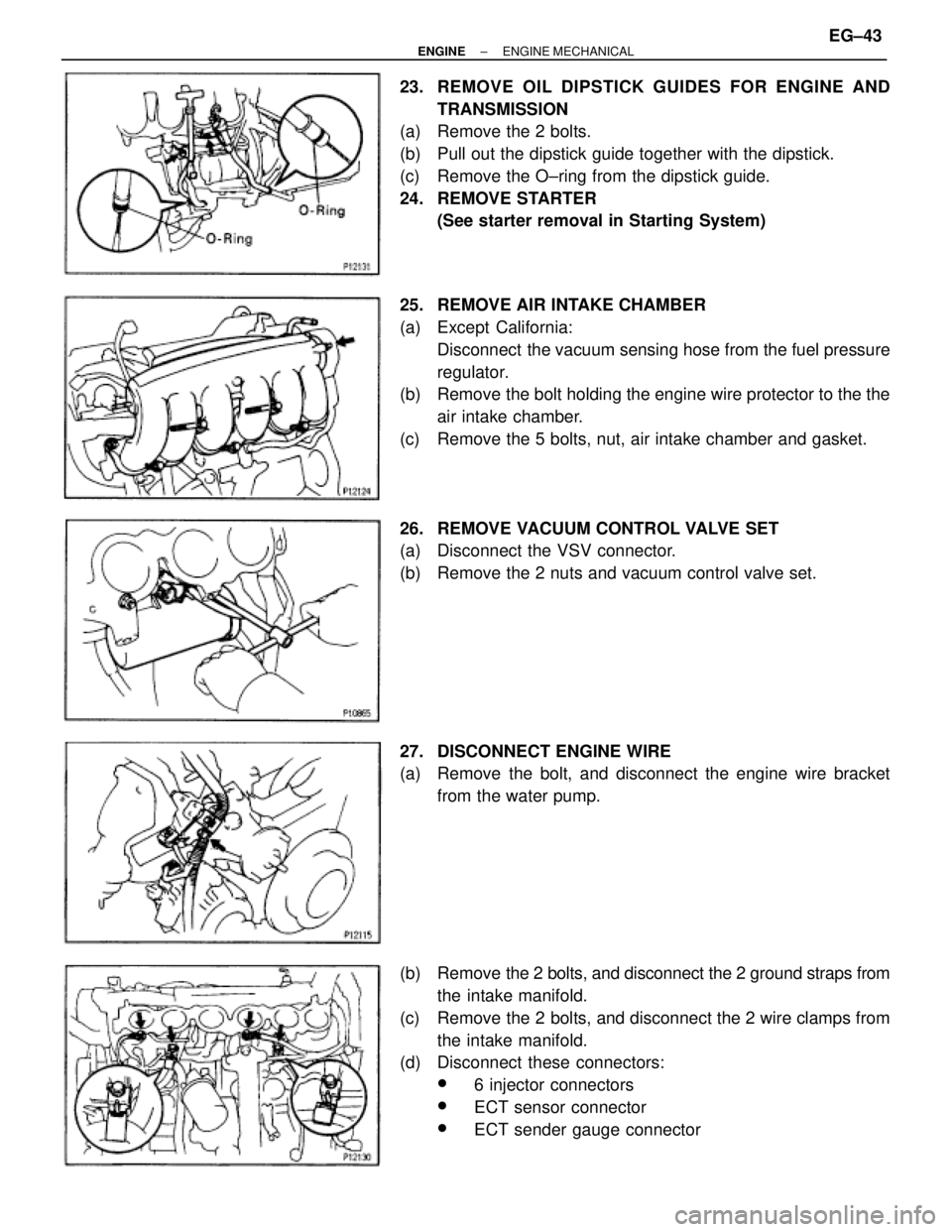
23. REMOVE OIL DIPSTICK GUIDES FOR ENGINE AND
TRANSMISSION
(a) Remove the 2 bolts.
(b) Pull out the dipstick guide together with the dipstick.
(c) Remove the O±ring from the dipstick guide.
24. REMOVE STARTER
(See starter removal in Starting System)
25. REMOVE AIR INTAKE CHAMBER
(a) Except California:
Disconnect the vacuum sensing hose from the fuel pressure
regulator.
(b) Remove the bolt holding the engine wire protector to the the
air intake chamber.
(c) Remove the 5 bolts, nut, air intake chamber and gasket.
26. REMOVE VACUUM CONTROL VALVE SET
(a) Disconnect the VSV connector.
(b) Remove the 2 nuts and vacuum control valve set.
27. DISCONNECT ENGINE WIRE
(a) Remove the bolt, and disconnect the engine wire bracket
from the water pump.
(b) Remove the 2 bolts, and disconnect the 2 ground straps from
the intake manifold.
(c) Remove the 2 bolts, and disconnect the 2 wire clamps from
the intake manifold.
(d) Disconnect these connectors:
w6 injector connectors
wECT sensor connector
wECT sender gauge connector
± ENGINEENGINE MECHANICALEG±43
Page 1381 of 2543
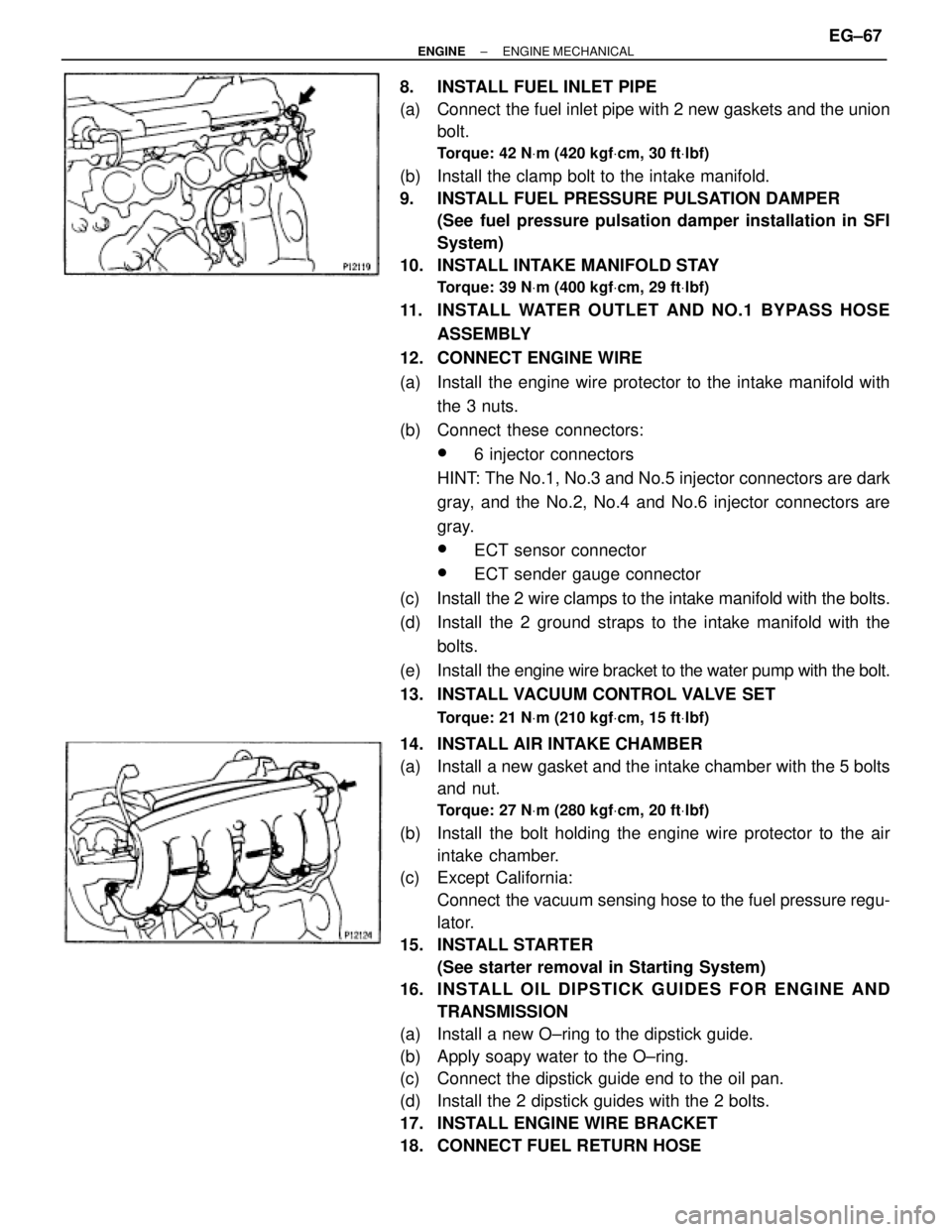
8. INSTALL FUEL INLET PIPE
(a) Connect the fuel inlet pipe with 2 new gaskets and the union
bolt.
Torque: 42 NVm (420 kgfVcm, 30 ftVlbf)
(b) Install the clamp bolt to the intake manifold.
9. INSTALL FUEL PRESSURE PULSATION DAMPER
(See fuel pressure pulsation damper installation in SFI
System)
10. INSTALL INTAKE MANIFOLD STAY
Torque: 39 NVm (400 kgfVcm, 29 ftVlbf)
11. INSTALL WATER OUTLET AND NO.1 BYPASS HOSE
ASSEMBLY
12. CONNECT ENGINE WIRE
(a) Install the engine wire protector to the intake manifold with
the 3 nuts.
(b) Connect these connectors:
w6 injector connectors
HINT: The No.1, No.3 and No.5 injector connectors are dark
gray, and the No.2, No.4 and No.6 injector connectors are
gray.
wECT sensor connector
wECT sender gauge connector
(c) Install the 2 wire clamps to the intake manifold with the bolts.
(d) Install the 2 ground straps to the intake manifold with the
bolts.
(e) Install the engine wire bracket to the water pump with the bolt.
13. INSTALL VACUUM CONTROL VALVE SET
Torque: 21 NVm (210 kgfVcm, 15 ftVlbf)
14. INSTALL AIR INTAKE CHAMBER
(a) Install a new gasket and the intake chamber with the 5 bolts
and nut.
Torque: 27 NVm (280 kgfVcm, 20 ftVlbf)
(b) Install the bolt holding the engine wire protector to the air
intake chamber.
(c) Except California:
Connect the vacuum sensing hose to the fuel pressure regu-
lator.
15. INSTALL STARTER
(See starter removal in Starting System)
16. INS TALL OIL DIP S TICK GUIDE S FO R ENG INE AND
TRANSMISSION
(a) Install a new O±ring to the dipstick guide.
(b) Apply soapy water to the O±ring.
(c) Connect the dipstick guide end to the oil pan.
(d) Install the 2 dipstick guides with the 2 bolts.
17. INSTALL ENGINE WIRE BRACKET
18. CONNECT FUEL RETURN HOSE
± ENGINEENGINE MECHANICALEG±67
Page 1394 of 2543
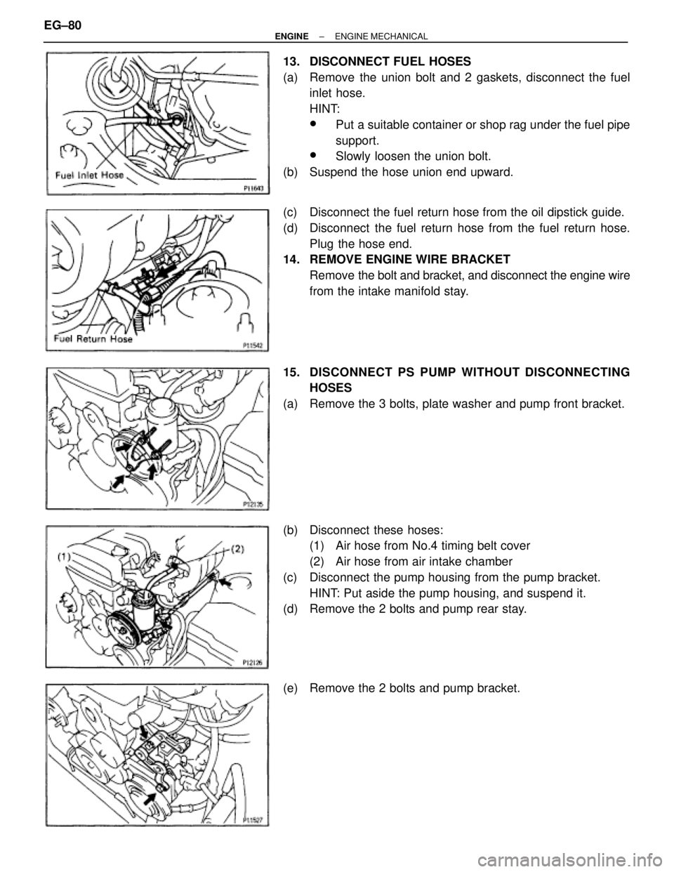
13. DISCONNECT FUEL HOSES
(a) Remove the union bolt and 2 gaskets, disconnect the fuel
inlet hose.
HINT:
wPut a suitable container or shop rag under the fuel pipe
support.
wSlowly loosen the union bolt.
(b) Suspend the hose union end upward.
(c) Disconnect the fuel return hose from the oil dipstick guide.
(d) Disconnect the fuel return hose from the fuel return hose.
Plug the hose end.
14. REMOVE ENGINE WIRE BRACKET
Remove the bolt and bracket, and disconnect the engine wire
from the intake manifold stay.
15. DISCONNECT PS PUMP WITHOUT DISCONNECTING
HOSES
(a) Remove the 3 bolts, plate washer and pump front bracket.
(b) Disconnect these hoses:
(1) Air hose from No.4 timing belt cover
(2) Air hose from air intake chamber
(c) Disconnect the pump housing from the pump bracket.
HINT: Put aside the pump housing, and suspend it.
(d) Remove the 2 bolts and pump rear stay.
(e) Remove the 2 bolts and pump bracket. EG±80
± ENGINEENGINE MECHANICAL
Page 1408 of 2543
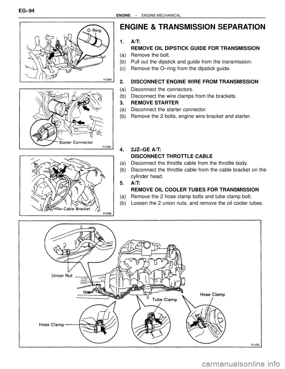
ENGINE & TRANSMISSION SEPARATION
1. A/T:
REMOVE OIL DIPSTICK GUIDE FOR TRANSMISSION
(a) Remove the bolt.
(b) Pull out the dipstick and guide from the transmission.
(c) Remove the O±ring from the dipstick guide.
2. DISCONNECT ENGINE WIRE FROM TRANSMISSION
(a) Disconnect the connectors.
(b) Disconnect the wire clamps from the brackets.
3. REMOVE STARTER
(a) Disconnect the starter connector.
(b) Remove the 2 bolts, engine wire bracket and starter.
4. 2JZ±GE A/T:
DISCONNECT THROTTLE CABLE
(a) Disconnect the throttle cable from the throttle body.
(b) Disconnect the throttle cable from the cable bracket on the
cylinder head.
5. A/T:
REMOVE OIL COOLER TUBES FOR TRANSMISSION
(a) Remove the 2 hose clamp bolts and tube clamp bolt.
(b) Loosen the 2 union nuts, and remove the oil cooler tubes.
EG±94± ENGINEENGINE MECHANICAL
Page 1439 of 2543
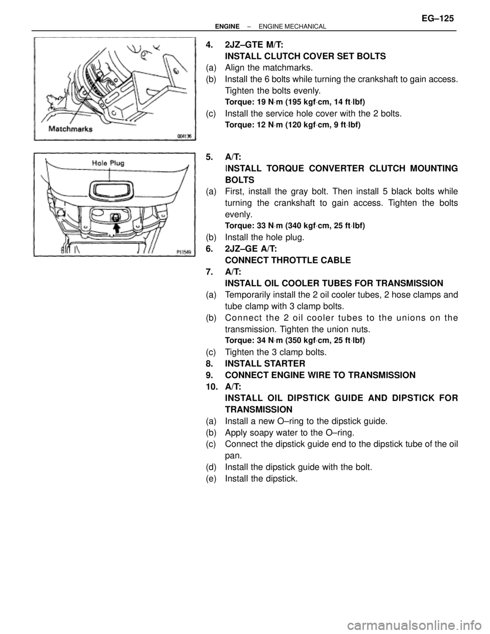
4. 2JZ±GTE M/T:
INSTALL CLUTCH COVER SET BOLTS
(a) Align the matchmarks.
(b) Install the 6 bolts while turning the crankshaft to gain access.
Tighten the bolts evenly.
Torque: 19 NVm (195 kgfVcm, 14 ftVlbf)
(c) Install the service hole cover with the 2 bolts.
Torque: 12 NVm (120 kgfVcm, 9 ftVlbf)
5. A/T:
INSTALL TORQUE CONVERTER CLUTCH MOUNTING
BOLTS
(a) First, install the gray bolt. Then install 5 black bolts while
turning the crankshaft to gain access. Tighten the bolts
evenly.
Torque: 33 NVm (340 kgfVcm, 25 ftVlbf)
(b) Install the hole plug.
6. 2JZ±GE A/T:
CONNECT THROTTLE CABLE
7. A/T:
INSTALL OIL COOLER TUBES FOR TRANSMISSION
(a) Temporarily install the 2 oil cooler tubes, 2 hose clamps and
tube clamp with 3 clamp bolts.
(b) Connect the 2 oil cooler tubes to the unions on the
transmission. Tighten the union nuts.
Torque: 34 NVm (350 kgfVcm, 25 ftVlbf)
(c) Tighten the 3 clamp bolts.
8. INSTALL STARTER
9. CONNECT ENGINE WIRE TO TRANSMISSION
10. A/T:
INSTALL OIL DIPSTICK GUIDE AND DIPSTICK FOR
TRANSMISSION
(a) Install a new O±ring to the dipstick guide.
(b) Apply soapy water to the O±ring.
(c) Connect the dipstick guide end to the dipstick tube of the oil
pan.
(d) Install the dipstick guide with the bolt.
(e) Install the dipstick.
± ENGINEENGINE MECHANICALEG±125
Page 1442 of 2543
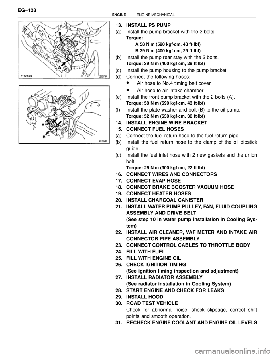
13. INSTALL PS PUMP
(a) Install the pump bracket with the 2 bolts.
Torque:
A 58 NVm (590 kgfVcm, 43 ftVlbf)
B 39 NVm (400 kgfVcm, 29 ftVlbf)
(b) Install the pump rear stay with the 2 bolts.
Torque: 39 NVm (400 kgfVcm, 29 ftVlbf)
(c) Install the pump housing to the pump bracket.
(d) Connect the following hoses:
wAir hose to No.4 timing belt cover
wAir hose to air intake chamber
(e) Install the front pump bracket with the 2 bolts (A).
Torque: 58 NVm (590 kgfVcm, 43 ftVlbf)
(f) Install the plate washer and bolt (B) to the oil pump.
Torque: 52 NVm (530 kgfVcm, 38 ftVlbf)
14. INSTALL ENGINE WIRE BRACKET
15. CONNECT FUEL HOSES
(a) Connect the fuel return hose to the fuel return pipe.
(b) Install the fuel return hose to the clamp of the oil dipstick
guide.
(c) Install the fuel inlet hose with 2 new gaskets and the union
bolt.
Torque: 29 NVm (300 kgfVcm, 22 ftVlbf)
16. CONNECT WIRES AND CONNECTORS
17. CONNECT EVAP HOSE
18. CONNECT BRAKE BOOSTER VACUUM HOSE
19. CONNECT HEATER HOSES
20. INSTALL CHARCOAL CANISTER
21. INSTALL WATER PUMP PULLEY, FAN, FLUID COUPLING
ASSEMBLY AND DRIVE BELT
(See step 10 in water pump installation in Cooling Sys-
tem)
22. INSTALL AIR CLEANER, VAF METER AND INTAKE AIR
CONNECTOR PIPE ASSEMBLY
23. CONNECT CONTROL CABLES TO THROTTLE BODY
24. FILL WITH FUEL
25. FILL WITH ENGINE OIL
26. CHECK IGNITION TIMING
(See ignition timing inspection and adjustment)
27. INSTALL RADIATOR ASSEMBLY
(See radiator installation in Cooling System)
28. START ENGINE AND CHECK FOR LEAKS
29. INSTALL HOOD
30. ROAD TEST VEHICLE
Check for abnormal noise, shock slippage, correct shift
points and smooth operation.
31. RECHECK ENGINE COOLANT AND ENGINE OIL LEVELS EG±128
± ENGINEENGINE MECHANICAL
Page 1445 of 2543
13. CONNECT ENGINE WIRE TO COWL PANEL
14. INSTALL A/C COMPRESSOR
(a) Using a torx socket (E10), install the stud bolt and and
compressor.
Torque: 26 NVm (265 kgfVcm, 19 ftVlbf)
(b) Connect the compressor connector.
(c) Temporarily install the compressor with nut and 3 bolts.
(d) Alternately tighten the bolt and nut.
Torque: 52 NVm (530 kgfVcm, 38 ftVlbf)
15. INSTALL PS PRESSURE TUBE
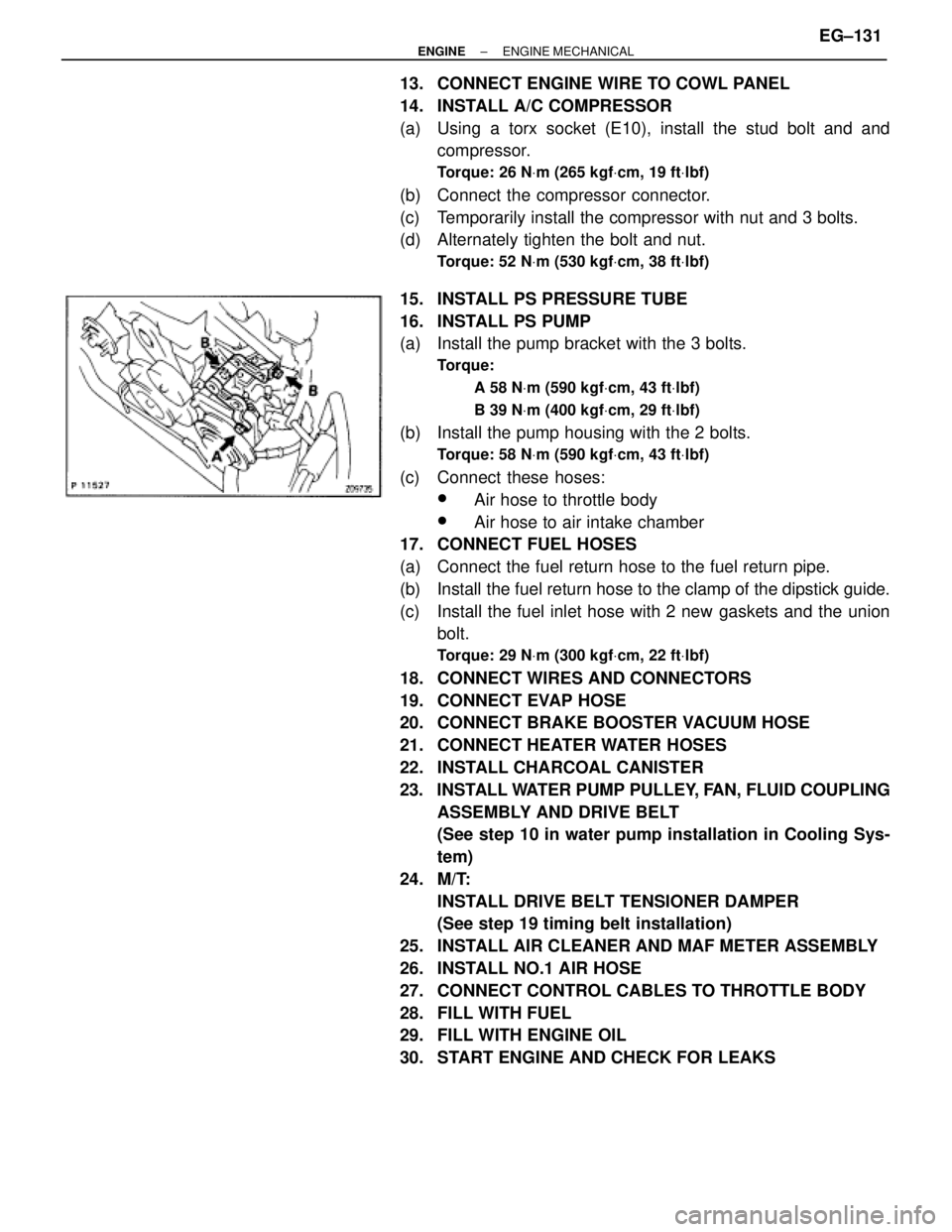
16. INSTALL PS PUMP
(a) Install the pump bracket with the 3 bolts.
Torque:
A 58 NVm (590 kgfVcm, 43 ftVlbf)
B 39 NVm (400 kgfVcm, 29 ftVlbf)
(b) Install the pump housing with the 2 bolts.
Torque: 58 NVm (590 kgfVcm, 43 ftVlbf)
(c) Connect these hoses:
wAir hose to throttle body
wAir hose to air intake chamber
17. CONNECT FUEL HOSES
(a) Connect the fuel return hose to the fuel return pipe.
(b) Install the fuel return hose to the clamp of the dipstick guide.
(c) Install the fuel inlet hose with 2 new gaskets and the union
bolt.
Torque: 29 NVm (300 kgfVcm, 22 ftVlbf)
18. CONNECT WIRES AND CONNECTORS
19. CONNECT EVAP HOSE
20. CONNECT BRAKE BOOSTER VACUUM HOSE
21. CONNECT HEATER WATER HOSES
22. INSTALL CHARCOAL CANISTER
23. INSTALL WATER PUMP PULLEY, FAN, FLUID COUPLING
ASSEMBLY AND DRIVE BELT
(See step 10 in water pump installation in Cooling Sys-
tem)
24. M/T:
INSTALL DRIVE BELT TENSIONER DAMPER
(See step 19 timing belt installation)
25. INSTALL AIR CLEANER AND MAF METER ASSEMBLY
26. INSTALL NO.1 AIR HOSE
27. CONNECT CONTROL CABLES TO THROTTLE BODY
28. FILL WITH FUEL
29. FILL WITH ENGINE OIL
30. START ENGINE AND CHECK FOR LEAKS
± ENGINEENGINE MECHANICALEG±131
Page 1480 of 2543

IF VEHICLE IS EQUIPPED WITH MOBIL
RADIO SYSTEM (HAM, CB, ETC.)
If the vehicle is equipped with a mobile communication sys-
tem, refer to the precaution in the IN section.
AIR INDUCTION SYSTEM
1. Separation of the engine oil dipstick, oil filler cap, PCV hose,
etc. may cause the engine to run out of tune.
2. Disconnection, looseness or cracks in the parts of the air
induction system between the throttle body and cylinder
head will cause air suction and cause the engine to run out
of tune.
ELECTRONIC CONTROL SYSTEM
1. Before removing SFI wiring connectors, terminals, etc., first
disconnect the power by either turning the ignition switch
OFF or disconnecting the negative (±) terminal cable from the
battery.
HINT: Always check the diagnostic trouble code before dis-
connecting the negative (±) terminal cable from the battery.
2. When installing the battery, be especially careful not to
incorrectly connect the positive (+) and negative (±) cables.
3. Do not permit parts to receive a severe impact during removal
or installation. Handle all SFI parts carefully, especially the
ECM.
4. Do not be careless during troubleshooting as there are
numerous transistor circuits and even slight terminal contact
can cause further troubles.
5. Do not open the ECM cover.
6. When inspecting during rainy weather, take care to prevent
entry of water. Also, when washing the engine compartment,
prevent water from getting on the SFI parts and wiring
connectors.
7. Parts should be replaced as an assembly.
8. Care is required when pulling out and inserting wiring
connectors.
(a) Release the lock and pull out the connector, pulling on the
connectors.
(b) Fully insert the connector and check that it is locked. EG±190
± ENGINESFI SYSTEMS (2JZ±GE)