Page 1519 of 2543
Vacuum Tank
COMPONENTS FOR REMOVAL AND
INSTALLATION
VACUUM TANK REMOVAL
Installation is in the reverse order of removal.
1. REMOVE OIL DIPSTICK AND GUIDE FOR A/T
(a) Remove the bolt.
(b) Pull out the dipstick guide together with the dipstick.
INSTALLATION HINT: Apply soapy water to the O±ring, and
push in the dipstick guide.
(c) Remove the O±ring from the dipstick guide.
INSTALLATION HINT: Use a new O±ring.
2. REMOVE VACUUM TANK AND VSV ASSEMBLY
(a) Remove the 2 nuts, and disconnect the vacuum tank from the
intake manifold.
Torque: 21 NVm (210 kgfVcm, 15 ftVlbf)
± ENGINESFI SYSTEM (2JZ±GE)EG±229
Page 1522 of 2543

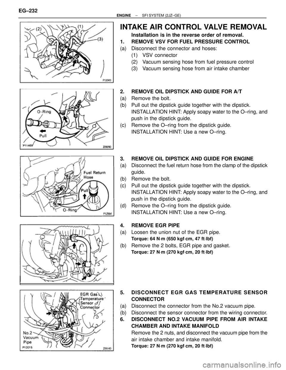
INTAKE AIR CONTROL VALVE REMOVAL
Installation is in the reverse order of removal.
1. REMOVE VSV FOR FUEL PRESSURE CONTROL
(a) Disconnect the connector and hoses:
(1) VSV connector
(2) Vacuum sensing hose from fuel pressure control
(3) Vacuum sensing hose from air intake chamber
2. REMOVE OIL DIPSTICK AND GUIDE FOR A/T
(a) Remove the bolt.
(b) Pull out the dipstick guide together with the dipstick.
INSTALLATION HINT: Apply soapy water to the O±ring, and
push in the dipstick guide.
(c) Remove the O±ring from the dipstick guide.
INSTALLATION HINT: Use a new O±ring.
3. REMOVE OIL DIPSTICK AND GUIDE FOR ENGINE
(a) Disconnect the fuel return hose from the clamp of the dipstick
guide.
(b) Remove the bolt.
(c) Pull out the dipstick guide together with the dipstick.
INSTALLATION HINT: Apply soapy water to the O±ring, and
push in the dipstick guide.
(d) Remove the O±ring from the dipstick guide.
INSTALLATION HINT: Use a new O±ring.
4. REMOVE EGR PIPE
(a) Loosen the union nut of the EGR pipe.
Torque: 64 NVm (650 kgfVcm, 47 ftVlbf)
(b) Remove the 2 bolts, EGR pipe and gasket.
Torque: 27 NVm (270 kgfVcm, 20 ftVlbf)
5. DISCONNECT EGR GAS TEMPERATURE SENSOR
CONNECTOR
(a) Disconnect the connector from the No.2 vacuum pipe.
(b) Disconnect the sensor connector from the wiring connector.
6. DISCONNECT NO.2 VACUUM PIPE FROM AIR INTAKE
CHAMBER AND INTAKE MANIFOLD
Remove the 2 nuts, and disconnect the vacuum pipe from the
air intake chamber and intake manifold.
Torque: 27 NVm (270 kgfVcm, 20 ftVlbf)
EG±232± ENGINESFI SYSTEM (2JZ±GE)
Page 1551 of 2543

IF VEHICLE IS EQUIPPED WITH MOBILE
RADIO SYSTEM (HAM, CB, ETC.)
If the vehicle is equipped with a mobile communication sys-
tem, refer to the precaution in the IN section.
AIR INDUCTION SYSTEM
1. Separation of the engine oil dipstick, oil filler cap, PCV hose,
etc. may cause the engine to run out of tune.
2. Disconnection, looseness or cracks in the parts of the air
induction system between the throttle body and cylinder
head will cause air suction and cause the engine to run out
of tune.
ELECTRONIC CONTROL SYSTEM
1. Before removing SFI wiring connectors, terminals, etc., first
disconnect the power by either turning the ignition switch
OFF or disconnecting the negative (±) terminal cable from the
battery.
HINT: Always check the diagnostic trouble code before dis-
connecting the negative (±) terminal cable from the battery.
2. When installing the battery, be especially careful not to
incorrectly connect the positive (+) and negative (±) cables.
3. Do not permit parts to receive a severe impact during removal
or installation. Handle all SFI parts carefully, especially the
ECM.
4. Do not be careless during troubleshooting as there are
numerous transistor circuits and even slight terminal contact
can cause further troubles.
5. Do not open the ECM cover.
6. When inspecting during rainy weather, take care to prevent
entry of water. Also, when washing the engine compartment,
prevent water from getting on the SFI parts and wiring
connectors.
7. Parts should be replaced as an assembly.
8. Care is required when pulling out and inserting wiring
connectors.
(a) Release the lock and pull out the connector, pulling on the
connectors.
(b) Fully insert the connector and check that it is locked.
± ENGINESFI SYSTEM (2JZ±GTE)EG±261
Page 1565 of 2543

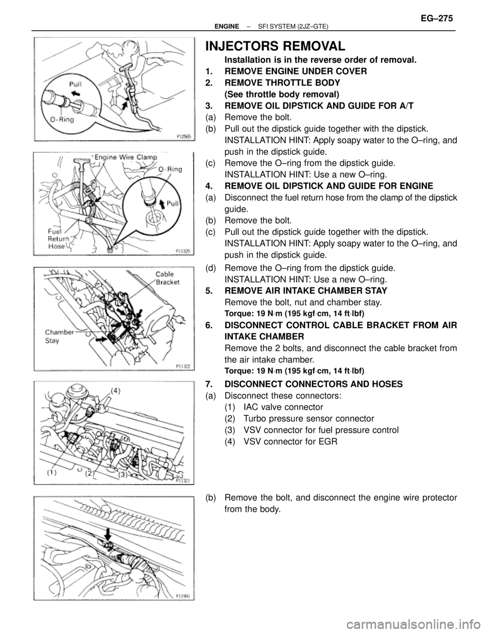
INJECTORS REMOVAL
Installation is in the reverse order of removal.
1. REMOVE ENGINE UNDER COVER
2. REMOVE THROTTLE BODY
(See throttle body removal)
3. REMOVE OIL DIPSTICK AND GUIDE FOR A/T
(a) Remove the bolt.
(b) Pull out the dipstick guide together with the dipstick.
INSTALLATION HINT: Apply soapy water to the O±ring, and
push in the dipstick guide.
(c) Remove the O±ring from the dipstick guide.
INSTALLATION HINT: Use a new O±ring.
4. REMOVE OIL DIPSTICK AND GUIDE FOR ENGINE
(a) Disconnect the fuel return hose from the clamp of the dipstick
guide.
(b) Remove the bolt.
(c) Pull out the dipstick guide together with the dipstick.
INSTALLATION HINT: Apply soapy water to the O±ring, and
push in the dipstick guide.
(d) Remove the O±ring from the dipstick guide.
INSTALLATION HINT: Use a new O±ring.
5. REMOVE AIR INTAKE CHAMBER STAY
Remove the bolt, nut and chamber stay.
Torque: 19 NVm (195 kgfVcm, 14 ftVlbf)
6. DISCONNECT CONTROL CABLE BRACKET FROM AIR
INTAKE CHAMBER
Remove the 2 bolts, and disconnect the cable bracket from
the air intake chamber.
Torque: 19 NVm (195 kgfVcm, 14 ftVlbf)
7. DISCONNECT CONNECTORS AND HOSES
(a) Disconnect these connectors:
(1) IAC valve connector
(2) Turbo pressure sensor connector
(3) VSV connector for fuel pressure control
(4) VSV connector for EGR
(b) Remove the bolt, and disconnect the engine wire protector
from the body.
± ENGINESFI SYSTEM (2JZ±GTE)EG±275
Page:
< prev 1-8 9-16 17-24