Page 2104 of 2543
(See page IN±30).
(1) Connect SST (check harness ªAº).
(See page EG±510)
SST 09990±01000
(2) Turn ignition switch ON.
Measure voltage between terminal FPU of engine
control module connector and body ground.
Voltage: 9 Ð 14 V
Check voltage between terminal FPU of engine control module
connector and body ground.
Proceed to next circuit inspection shown
on matrix chart (See page Eg±514).
Repair or replace harness or connector.
Check for open and short in harness and connector between engine control
module and VSV, VSV and EFI main relay (See page IN±30).
Check and replace engine control module.
± ENGINE2JZ±GTE ENGINE TROUBLESHOOTINGEG±597
Page 2106 of 2543

(See page IN±30).
Turn ignition switch ON.
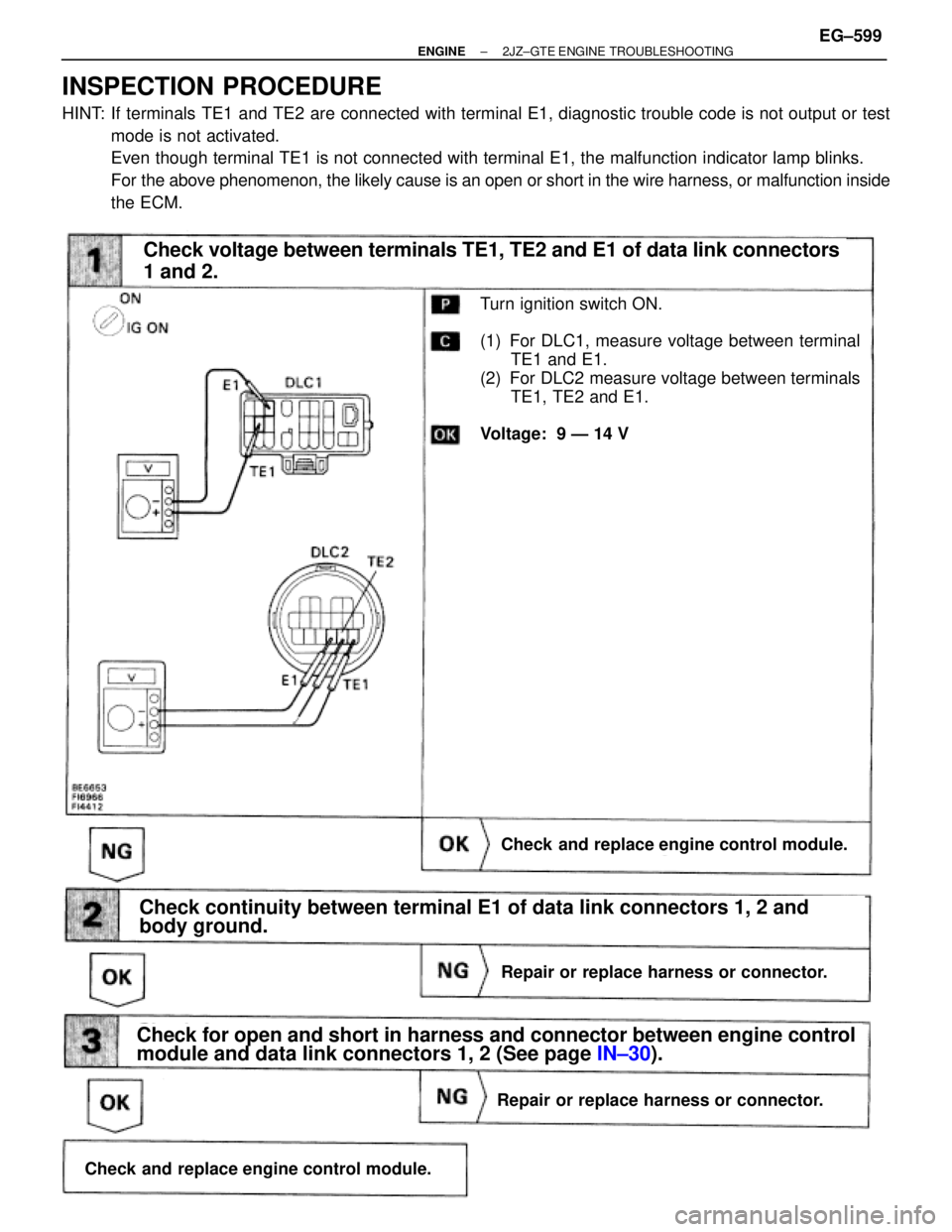
(1) For DLC1, measure voltage between terminal
TE1 and E1.
(2) For DLC2 measure voltage between terminals
TE1, TE2 and E1.
Voltage: 9 Ð 14 V
Check voltage between terminals TE1, TE2 and E1 of data link connectors
1 and 2.
Check and replace engine control module.
Repair or replace harness or connector.
Check for open and short in harness and connector between engine control
module and data link connectors 1, 2 (See page IN±30).
Repair or replace harness or connector.
Check and replace engine control module.
Check continuity between terminal E1 of data link connectors 1, 2 and
body ground.
INSPECTION PROCEDURE
HINT: If terminals TE1 and TE2 are connected with terminal E1, diagnostic trouble code is not output or test
mode is not activated.
Even though terminal TE1 is not connected with terminal E1, the malfunction indicator lamp blinks.
For the above phenomenon, the likely cause is an open or short in the wire harness, or malfunction inside
the ECM.
± ENGINE2JZ±GTE ENGINE TROUBLESHOOTINGEG±599
Page 2109 of 2543

TROUBLESHOOTING
HINT: Before troubleshooting the turbocharger, first check the engine itself. (Valve clearance, engine com-
pression, ignition timing etc.)
Check intake air system, and repair or replace parts
as necessary. (See page
EG±144)
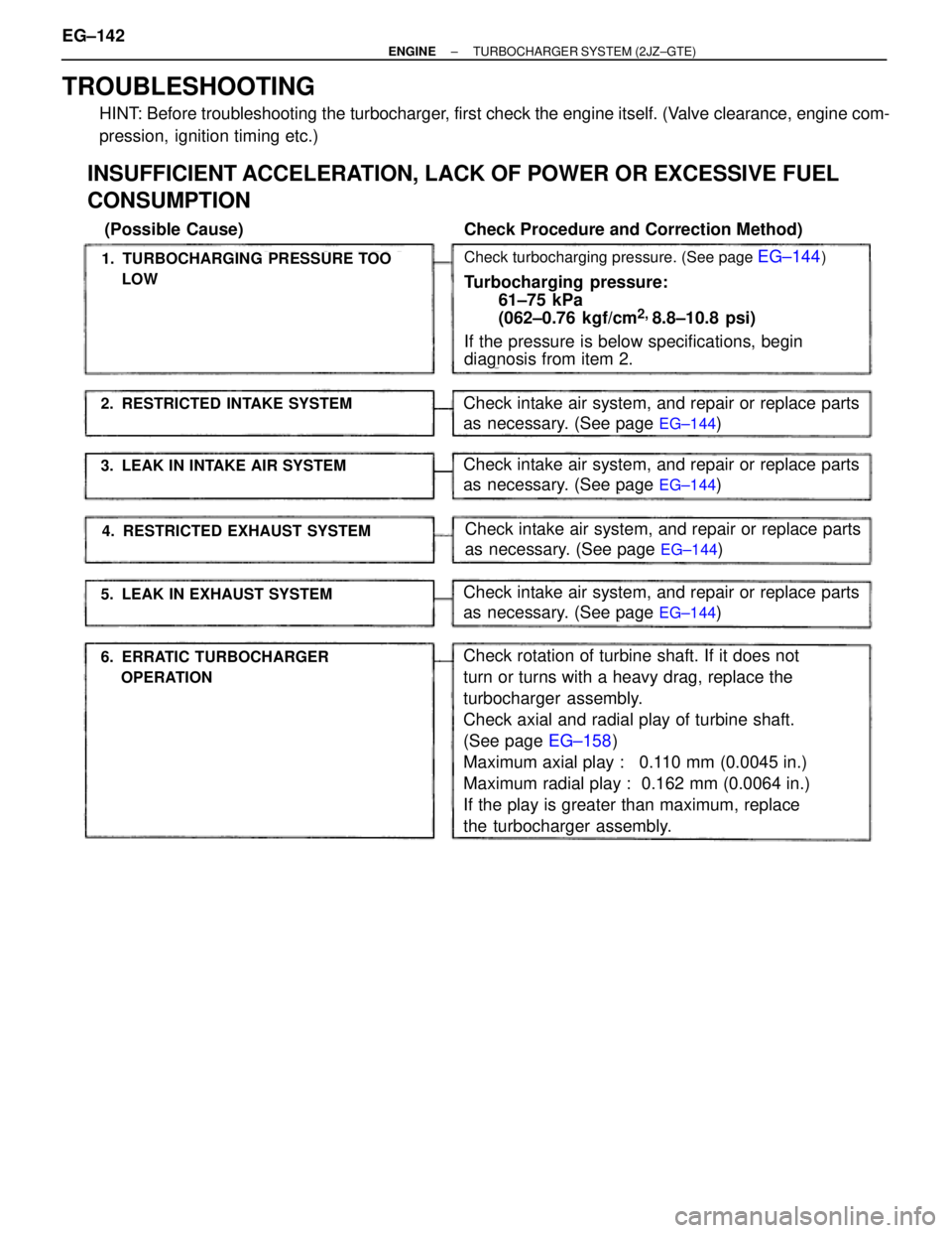
1. TURBOCHARGING PRESSURE TOO
LOW
2. RESTRICTED INTAKE SYSTEM
6. ERRATIC TURBOCHARGER
OPERATION
3. LEAK IN INTAKE AIR SYSTEM
4. RESTRICTED EXHAUST SYSTEM
5. LEAK IN EXHAUST SYSTEM
INSUFFICIENT ACCELERATION, LACK OF POWER OR EXCESSIVE FUEL
CONSUMPTION
(Possible Cause) Check Procedure and Correction Method)
Check turbocharging pressure. (See page EG±144)
Turbocharging pressure:
61±75 kPa
(062±0.76 kgf/cm
2,
8.8±10.8 psi)
If the pressure is below specifications, begin
diagnosis from item 2.
Check intake air system, and repair or replace parts
as necessary. (See page
EG±144)
Check intake air system, and repair or replace parts
as necessary. (See page
EG±144)
Check intake air system, and repair or replace parts
as necessary. (See page
EG±144)
Check rotation of turbine shaft. If it does not
turn or turns with a heavy drag, replace the
turbocharger assembly.
Check axial and radial play of turbine shaft.
(See page EG±158)
Maximum axial play : 0.110 mm (0.0045 in.)
Maximum radial play : 0.162 mm (0.0064 in.)
If the play is greater than maximum, replace
the turbocharger assembly. EG±142
± ENGINETURBOCHARGER SYSTEM (2JZ±GTE)
Page 2135 of 2543
![TOYOTA SUPRA 1995 Service Repair Manual To Ignition SW
IG Terminal
Fuse
Relay
SW2 SolenoidVoltmeter [A]
[B]
[C] SW1
Ohmmeter
SW
INTRODUCTION±HOW TO PERFORM FOR SYSTEM INSPECTION
A±5
6
Wire Harness Repair Manual (RM1022E)
HOW TO PERFORM FO TOYOTA SUPRA 1995 Service Repair Manual To Ignition SW
IG Terminal
Fuse
Relay
SW2 SolenoidVoltmeter [A]
[B]
[C] SW1
Ohmmeter
SW
INTRODUCTION±HOW TO PERFORM FOR SYSTEM INSPECTION
A±5
6
Wire Harness Repair Manual (RM1022E)
HOW TO PERFORM FO](/manual-img/14/57468/w960_57468-2134.png)
To Ignition SW
IG Terminal
Fuse
Relay
SW2 SolenoidVoltmeter [A]
[B]
[C] SW1
Ohmmeter
SW
INTRODUCTION±HOW TO PERFORM FOR SYSTEM INSPECTION
A±5
6
Wire Harness Repair Manual (RM1022E)
HOW TO PERFORM FOR SYSTEM INSPECTION
This inspection procedure is a simple troubleshooting which should be carried out on the vehicle during
system operation and is based on the assumption of system component trouble
Always inspect the trouble taking the following items into consideration:
�Ground point fault
�Open or short circuit of the wire harness
�Connector or terminal connection fault
�Fuse or fusible link fault
NOTICE:
�This is an on±vehicle inspection during system operation.
Therefore, inspect the trouble with due regard for safety.
�If connecting the battery directly, be careful not to cause a short circuit, and select the applicable
voltage.
1. Voltage Check
(a)Establish conditions in which voltage is present at the
check point.
Example:
[A] ± Ignition SW on
[B] ± Ignition SW and SW 1 on
[C] ± Ignition SW, SW 1 and Relay on (SW 2 off)
(b)Using a voltmeter, connect the negative (±) lead to a
good ground point or negative (±) battery terminal
and the positive (+) lead to the connector or
component terminal. This check can be done with a
test bulb instead of a voltmeter.
2. Continuity and Resistance Check
(a)Disconnect the battery terminal or wire so there is no
voltage between the check points.
(b)Contact the two leads of an ohmmeter to each of the
check points.
A
Page 2137 of 2543
![TOYOTA SUPRA 1995 Service Repair Manual Fuse Case Test Bulb
Short [A]
SW1
Short [B]
Relay
Light
Short [C]
SW2 SolenoidDisconnect
Disconnect DisconnectTo Ignition SW
IG Terminal
INTRODUCTION±HOW TO PERFORM FOR SYSTEM INSPECTION
A±7
8
Wire TOYOTA SUPRA 1995 Service Repair Manual Fuse Case Test Bulb
Short [A]
SW1
Short [B]
Relay
Light
Short [C]
SW2 SolenoidDisconnect
Disconnect DisconnectTo Ignition SW
IG Terminal
INTRODUCTION±HOW TO PERFORM FOR SYSTEM INSPECTION
A±7
8
Wire](/manual-img/14/57468/w960_57468-2136.png)
Fuse Case Test Bulb
Short [A]
SW1
Short [B]
Relay
Light
Short [C]
SW2 SolenoidDisconnect
Disconnect DisconnectTo Ignition SW
IG Terminal
INTRODUCTION±HOW TO PERFORM FOR SYSTEM INSPECTION
A±7
8
Wire Harness Repair Manual (RM1022E)
4. Finding a Short Circuit
(a)Remove the blown fuse and eliminate all loads from
the fuse.
(b)Connect a test bulb in place of the fuse.
(c)Establish conditions in which the test bulb comes on.
Example:
[A] ± Ignition SW on
[B] ± Ignition SW and SW 1 on
[C] ± Ignition SW, SW 1 and Relay on (Connect the Relay)
and SW 2 off (or disconnect SW 2)
(d)Disconnect and reconnect the connectors while
watching the test bulb. The short lies between the
connector where the test bulb stays lit and the
connector where the bulb goes out.
(e)Find the exact location of the short by lightly shaking
the problem wire along the body.
CAUTION:
(a)Do not open the cover or the case of the ECU
unless absolutely necessary. (If the IC terminals
are touched, the IC may be destroyed by static
electricity.)
(b)When replacing the internal mechanism (ECU
part) of the digital meter, be careful that no part of
your body or clothing comes in contact with the
terminals of leads from the IC, etc. of the
replacement part (spare part).
A
Page 2139 of 2543
Equal Amperage Rating
Equal Amperage Rating
Puller
INTRODUCTION±CIRCUIT PROTECTION
A±9
10
Wire Harness Repair Manual (RM1022E)
REPLACEMENT OF FUSE AND FUSIBLE LINK
HINT: If replacing the fuse or fusible link, be sure to
replace it with a fuse or fusible link with an equal amperage
rating.
NOTICE:
1.Turn off all electrical components and the ignition
switch before replacing a fuse or fusible link. Do
not exceed the fuse or fusible link amperage rating.
2.Always use a fuse puller for removing and
inserting a fuse. Remove and insert straight in and
out without twisting. Twisting could force open the
terminals too much, resulting in a bad connection.
If a fuse or fusible link continues to blow, a short circuit is
indicated. The system must be checked by a qualified
technician.
HINT: The puller is located at Junction Block No.2.
A