Page 2089 of 2543
INSPECTION PROCEDURE
(See page EG±510)
Check and repair harness or connector between
engine control module and EFI No.1 fuse, EFI No.1
fuse and battery.
Remove EFI No.1 fuse from R/B No.2.
Check continuity of EFI No.1 fuse.
Continuity
Check EFI No.1 Fuse.
Check voltage between terminal BATT of engine control module connector
and body ground.
Connect SST (check harness ªAº).
See page EG±510)
SST 09990±01000
Measure voltage between terminal BATT of en-
gine control module connector and body ground.
Voltage: 9 Ð 14 V
Check for short in the harness and all the compo-
nents connected to EFI No.1 fuse (See attached
wiring diagram).
Are the diagnostic trouble codes still in the memory when the ignition switch
is turned OFF?
Check and replace engine control module.
Proceed to next circuit inspection shown on matrix
chart (See page EG±514).
EG±582± ENGINE2JZ±GTE ENGINE TROUBLESHOOTING
Page 2130 of 2543
�2002
All rights reserved. This book may not be
reproduced or copied, in whole or in part, without the
written permission of Toyota Motor Corporation.
FOREWORD
This manual has been prepared for use when
performing terminal repairs, wire repairs, or connector
repairs on vehicles.
A step±by±step section on connector repair and
terminal repair is included.
There is a section of charts with terminal and connector
illustrations, part numbers, and notes on terminal
removal.
By using this guide, a satisfactory repair of the wiring
harness and connectors in Toyota vehicles will be easy
to achieve.
All information in this manual is based on the latest
product information at the time of publication. However,
specifications and procedures are subject to change
without notice.
Page 2132 of 2543

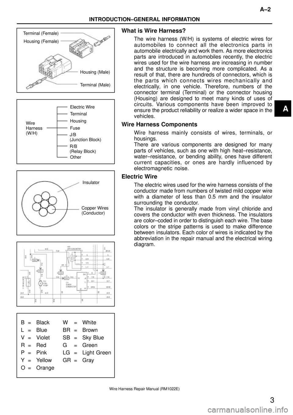
Terminal (Female)
Housing (Female)
Housing (Male)
Terminal (Male)
Wire
Harness
(W/H)Electric Wire
Terminal
Housing
Fuse
Other J/B
(Junction Block)
R/B
(Relay Block)
Insulator
Copper Wires
(Conductor)
B = Black W = White
L = Blue BR = Brown
V = Violet SB = Sky Blue
R = Red G = Green
P = Pink LG = Light Green
Y = Yellow GR = Gray
O = Orange
A±2
INTRODUCTION±GENERAL INFORMATION
3
Wire Harness Repair Manual (RM1022E)
What is Wire Harness?
The wire harness (W/H) is systems of electric wires for
automobiles to connect all the electronics parts in
automobile electrically and work them. As more electronics
parts are introduced in automobiles recently, the electric
wires used for the wire harness are increasing in number
and the structure is becoming more complicated. As a
result of that, there are hundreds of connectors, which is
the parts which connects wires mechanically and
electrically, in one vehicle. Therefore, numbers of the
connector terminal (Terminal) or the connector housing
(Housing) are designed to meet many kinds of uses of
circuits. Various components have been improved to
ensure the product reliability or realize a wider space in the
vehicles.
Wire Harness Components
Wire harness mainly consists of wires, terminals, or
housings.
There are various components are designed for many
parts of vehicles, such as one with high heat±resistance,
water±resistance, or bending ability, ones have different
current capacities, or ones are hardly influenced by
electromagnetic noise.
Electric Wire
The electric wires used for the wire harness consists of the
conductor made from numbers of twisted mild copper wire
with a diameter of less than 0.5 mm and the insulator
surrounding the conductor.
The insulator is generally made from vinyl chloride and
covers the conductor with even thickness. The insulators
are color±coded in order to distinguish each wire. The base
colors or the stripe patterns is used to make difference
between insulators. Each color of wires is indicated by the
abbreviation in the repair manual and the electrical wiring
diagram.
A
Page 2138 of 2543

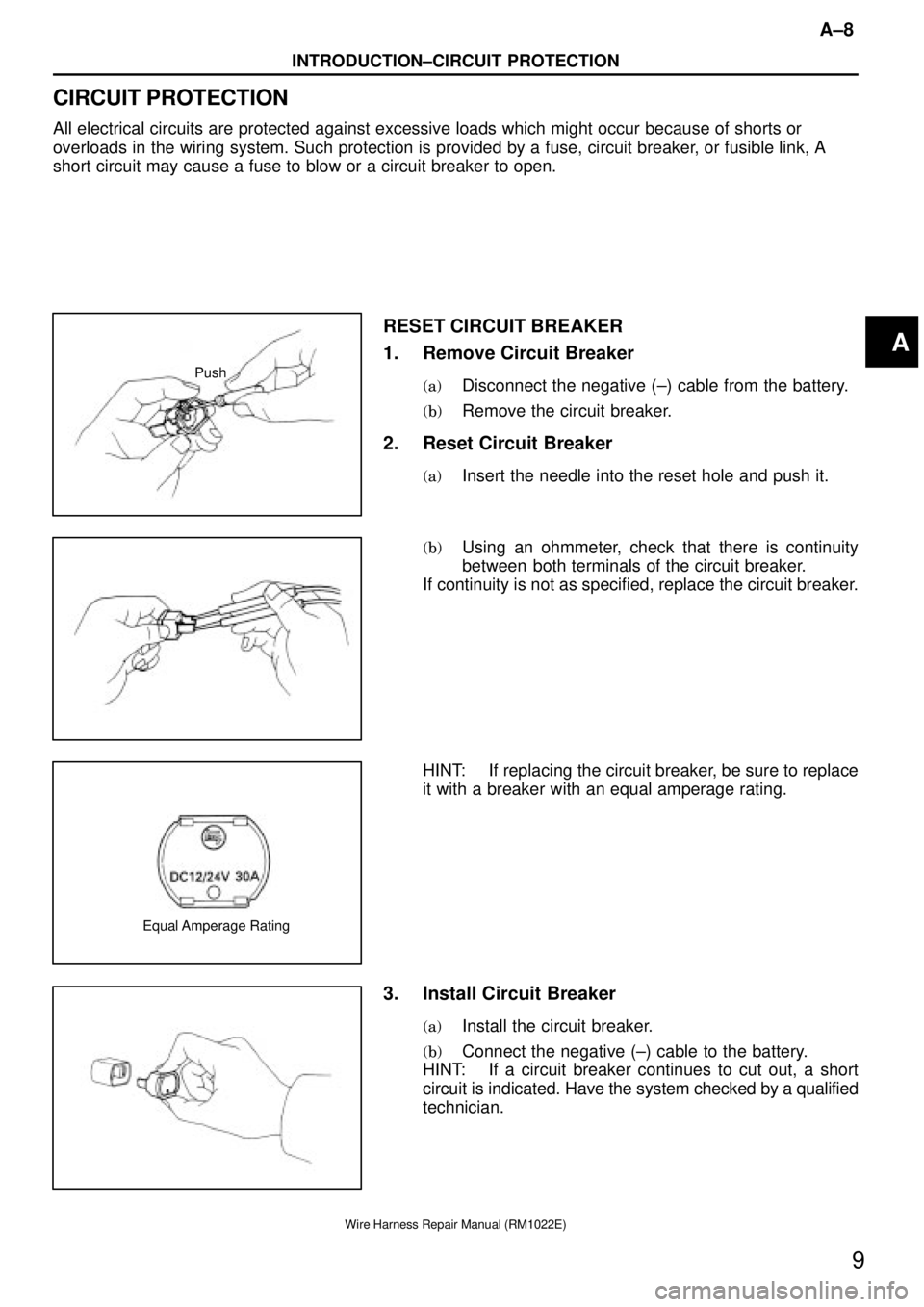
Push
Equal Amperage Rating
A±8
INTRODUCTION±CIRCUIT PROTECTION
9
Wire Harness Repair Manual (RM1022E)
CIRCUIT PROTECTION
All electrical circuits are protected against excessive loads which might occur because of shorts or
overloads in the wiring system. Such protection is provided by a fuse, circuit breaker, or fusible link, A
short circuit may cause a fuse to blow or a circuit breaker to open.
RESET CIRCUIT BREAKER
1. Remove Circuit Breaker
(a)Disconnect the negative (±) cable from the battery.
(b)Remove the circuit breaker.
2. Reset Circuit Breaker
(a)Insert the needle into the reset hole and push it.
(b)Using an ohmmeter, check that there is continuity
between both terminals of the circuit breaker.
If continuity is not as specified, replace the circuit breaker.
HINT: If replacing the circuit breaker, be sure to replace
it with a breaker with an equal amperage rating.
3. Install Circuit Breaker
(a)Install the circuit breaker.
(b)Connect the negative (±) cable to the battery.
HINT: If a circuit breaker continues to cut out, a short
circuit is indicated. Have the system checked by a qualified
technician.
A