Page 459 of 2543
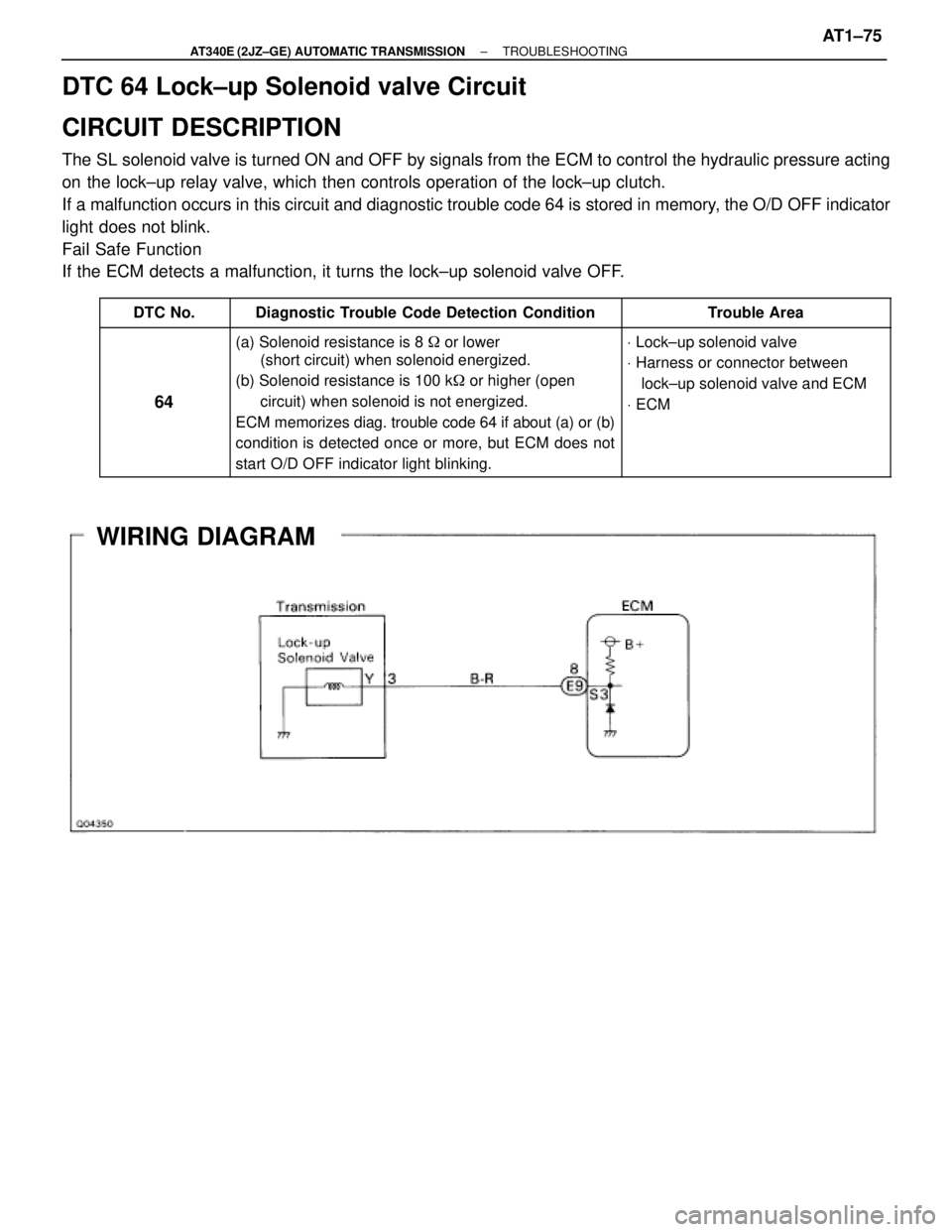
WIRING DIAGRAM
± AT340E (2JZ±GE) AUTOMATIC TRANSMISSIONTROUBLESHOOTINGAT1±73
Page 461 of 2543

DTC 64 Lock±up Solenoid valve Circuit
CIRCUIT DESCRIPTION
The SL solenoid valve is turned ON and OFF by signals from the ECM to control the hydraulic pressure acting
on the lock±up relay valve, which then controls operation of the lock±up clutch.
If a malfunction occurs in this circuit and diagnostic trouble code 64 is stored in memory, the O/D OFF indicator
light does not blink.
Fail Safe Function
If the ECM detects a malfunction, it turns the lock±up solenoid valve OFF.
������ ������DTC No.����������������� �����������������Diagnostic Trouble Code Detection Condition������������ ������������Trouble Area
������ �
����� �
����� �
����� �
����� �
����� ������
64
����������������� �
���������������� �
���������������� �
���������������� �
���������������� �
���������������� �����������������
(a) Solenoid resistance is 8 � or lower
(short circuit) when solenoid energized.
(b) Solenoid resistance is 100 k� or higher (open
circuit) when solenoid is not energized.
ECM memorizes diag. trouble code 64 if about (a) or (b)
condition is detected once or more, but ECM does not
start O/D OFF indicator light blinking.������������
������������
������������
������������
������������
������������ ������������
V Lock±up solenoid valve
V Harness or connector between
lock±up solenoid valve and ECM
V ECM
WIRING DIAGRAM
± AT340E (2JZ±GE) AUTOMATIC TRANSMISSIONTROUBLESHOOTINGAT1±75
Page 463 of 2543
Throttle Position Sensor Circuit
CIRCUIT DESCRIPTION
The throttle position sensor detects the throttle valve opening angle and sends signals to ECM.
WIRING DIAGRAM
± AT340E (2JZ±GE) AUTOMATIC TRANSMISSIONTROUBLESHOOTINGAT1±77
Page 465 of 2543
Kick±down Switch Circuit
CIRCUIT DESCRIPTION
The kick±down switch is turned on when the accelerator pedal
is depressed beyond the full throttle opening and sends signals
to ECM.
When the kick±down switch is turned on, the ECM controls gear
shifting according to the programmed shift diagrams.
If a short circuit develops in the kick±down switch, the ECM dis-
regards the kick±down signals and controls shifting at the nor-
mal shift points.
WIRING DIAGRAM
± AT340E (2JZ±GE) AUTOMATIC TRANSMISSIONTROUBLESHOOTINGAT1±79
Page 467 of 2543
Park Neutral Position Switch Circuit
CIRCUIT DESCRIPTION
The park/neutral position switch detects the shift lever position and sends signals to ECM.
The ECM receives signals (NSW, 2 and L) from the park/neutral position switch. When the signal is not sent
to the ECM from the park/neutral position switch, the ECM judges that the shift lever is in the D position.
WIRING DIAGRAM
± AT340E (2JZ±GE) AUTOMATIC TRANSMISSIONTROUBLESHOOTINGAT1±81
Page 469 of 2543
See
Stop Light Switch Circuit
CIRCUIT DESCRIPTION
The purpose of this circuit is to prevent the engine from stalling, while driving in lock±up condition, when brakes
are suddenly applied.
When the brake pedal is operated, this switch sends a signal to ECM. Then the ECM cancels operation of the
lock±up clutch while braking is in progress.
WIRING DIAGRAM
INSPECTION PROCEDURE
Check operation of stop light.
Check and repair stop light circuit.
Check if the stop lights go on and off normally when the brake pedal is depressed and
released.
± AT340E (2JZ±GE) AUTOMATIC TRANSMISSIONTROUBLESHOOTINGAT1±83
Page 471 of 2543
Pattern Select Switch Circuit
CIRCUIT DESCRIPTION
The ECM memory contains the shift programs for the NORMAL and MANUAL patterns, 2 position, and L posi-
tion and the lock±up patterns. Following the programs corresponding to the signals from the pattern select
switch, the park/neutral position switch and other various sensors the ECM switches the solenoid valves ON
and OFF, thereby controlling the transmission gear change and the lock±up clutch operation.
WIRING DIAGRAM
INSPECTION PROCEDURE
Check A/T fluid temp. sensor. (See page AT1±64).
Replace A/T fluid temp. sensor.
± AT340E (2JZ±GE) AUTOMATIC TRANSMISSIONTROUBLESHOOTINGAT1±85
Page 474 of 2543
O D Main Switch & O D OFF Indicator Light Circuit
CIRCUIT DESCRIPTION
The O/D main switch contacts go off when the switch is pushed in and come on when it is pushed out. In O/D
main switch OFF position, the O/D OFF indicator light lights up, and the ECM prohibits shifting to overdrive. The
ECM also causes the O/D OFF indicator light to blink when a malfunction is detected. In this case, connecting
the terminals in the DLC2 or DLC1 can display the malfunction code.
WIRING DIAGRAM
AT1±88± AT340E (2JZ±GE) AUTOMATIC TRANSMISSIONTROUBLESHOOTING