Page 118 of 2543

INTRODUCTIONGLOSSARY OF SAE AND TOYOTA TERMS -
IN-7
GLOSSARY OF SAE AND TOYOTA TERMS
This glossary lists all SAE-J1930 terms and abbreviations used in this manual in compliance with SAE
recommendations, as well as their Toyota equivalents.
SAE
ABBREVIATIONSSAE TERMSTOYOTA TERMS
( )--ABBREVIATIONS
A/CAir ConditioningAir Conditioner
ACLAir CleanerAir Cleaner
AIRSecondary Air InjectionAir Injection (AI)
APAccelerator Pedal-
B+Battery Positive Voltage+B, Battery Voltage
BAROBarometric Pressure-
CACCharge Air CoolerIntercooler
CARBCarburetorCarburetor
CFIContinuous Fuel Injection-
CKPCrankshaft PositionCrank Angle
CLClosed LoopClosed Loop
CMPCamshaft PositionCam Angle
CPPClutch Pedal Position-
CTOXContinuous Trap Oxidizer-
CTPClosed Throttle Position-
DFIDirect Fuel Injection (Diesel)Direct Injection (DI)
DIDistributor Ignition-
DLC1
DLC2
DLC3Data Link Connector 1
Data Link Connector 2
Data Link Connector 31: Check Connector
2: Toyota Diagnosis Communication Link (TDCL)
3: OBD II Diagnostic Connector
DTCDiagnostic Trouble CodeDiagnostic Code
DTMDiagnostic Test Mode-
ECLEngine Control Level-
ECMEngine Control ModuleEngine ECU (Electronic Control Unit)
ECTEngine Coolant TemperatureCoolant Temperature, Water Temperature (THW)
EEPROMElectrically Erasable Programmable Read Only
MemoryElectrically Erasable Programmable Read Only Memory
(EEPROM),
Erasable Programmable Read Only Memory(EPROM)
EFEEarly Fuel EvaporationCold Mixture Heater (CMH), Heat Control Valve (HCV)
EGRExhaust Gas RecirculationExhaust Gas Recirculation (EGR)
EIElectronic IgnitionToyota Distributorless Ignition (TDI)
EMEngine ModificationEngine Modification (EM)
EPROMErasable Programmable Read Only MemoryProgrammable Read Only Memory (PROM)
EVAPEvaporative EmissionEvaporative Emission Control (EVAP)
FCFan Control-
FEEPROMFlash Electrically Erasable Programmable
Read Only Memory-
FEPROMFlash Erasable Programmable Read Only Memory-
FFFlexible Fuel-
FPFuel PumpFuel Pump
GENGeneratorAlternator
GNDGroundGround (GND)
HO2SHeated Oxygen SensorHeated Oxygen Sensor (HO2S)
IN016-02
Page 491 of 2543

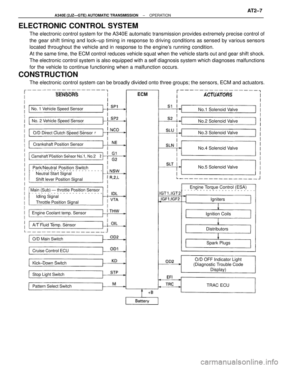
ELECTRONIC CONTROL SYSTEM
The electronic control system for the A340E automatic transmission provides extremely precise control of
the gear shift timing and lock±up timing in response to driving conditions as sensed by various sensors
located throughout the vehicle and in response to the engine's running condition.
At the same time, the ECM control reduces vehicle squat when the vehicle starts out and gear shift shock.
The electronic control system is also equipped with a self diagnosis system which diagnoses malfunctions
for the vehicle to continue functioning when a malfunction occurs.
CONSTRUCTION
The electronic control system can be broadly divided onto three groups; the sensors, ECM and actuators.
No. 1 Vehicle Speed Sensor
No. 2 Vehicle Speed Sensor
Crankshaft Position Sensor
Camshaft Position Sensor No.1, No.2
Park/Neutral Position Switch
� Neutral Start Signal
� Shift lever Position Signal
� Idling Signal
� Throttle Position Signal
Main (Sub) Ð throttle Position Sensor
Engine Coolant temp. Sensor
A/T Fluid Temp. Sensor
O/D Main Switch
Cruise Control ECU
Kick±Down Switch
Stop Light Switch
Pattern Select Switch
SENSORSECMACTUATORS
No.1 Solenoid Valve
No.2 Solenoid Valve
No.3 Solenoid Valve
No.4 Solenoid Valve
No.5 Solenoid Valve
Engine Torque Control (ESA)
Igniters
Ignition Coils
Distributors
Spark Plugs
O/D OFF Indicator Light
(Diagnostic Trouble Code
Display)
TRAC ECU
O/D Direct Clutch Speed Sensor
± A340E (2JZÐGTE) AUTOMATIC TRANSMISSIONOPERATIONAT2±7
Page 494 of 2543

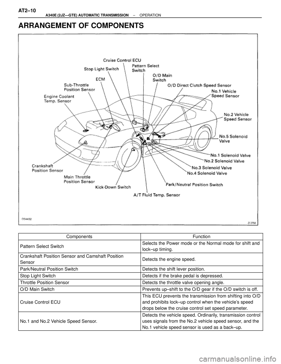
ARRANGEMENT OF COMPONENTS
������������������Components�������������������Function������������������ �
����������������� ������������������Pattern Select Switch
������������������� �
������������������ �������������������Selects the Power mode or the Normal mode for shift and
lock±up timing.
������������������ �
����������������� ������������������Crankshaft Position Sensor and Camshaft Position
Sensor������������������� �
������������������ �������������������Detects the engine speed.
������������������ ������������������Park/Neutral Position Switch������������������� �������������������Detects the shift lever position.
������������������ ������������������Stop Light Switch������������������� �������������������Detects if the brake pedal is depressed.
������������������ ������������������Throttle Position Sensor������������������� �������������������Detects the throttle valve opening angle.
������������������ ������������������O/D Main Switch������������������� �������������������Prevents up±shift to the O/D gear if the O/D switch is off.
������������������ �
����������������� �
����������������� ������������������
Cruise Control ECU
������������������� �
������������������ �
������������������ �������������������
This ECU prevents the transmission from shifting into O/D
and prohibits lock±up control when the vehicle's speed
drops below the cruise control set speed parameter.
������������������ �
����������������� ������������������No.1 and No.2 Vehicle Speed Sensor.
������������������� �
������������������ �������������������
Detects the vehicle speed. Ordinarily, transmission control
uses signals from the No.2 vehicle speed sensor, and the
No.1 vehicle speed sensor is used as a back±up.
AT2±10± A340E (2JZÐGTE) AUTOMATIC TRANSMISSIONOPERATION
Page 1038 of 2543
1. Check that the battery cables are connected to the correct terminals.
2. Disconnect the battery cables when the battery is given a quick charge.
3. Do not do these tests with a high voltage insulation resistance tester.
4. Never disconnect the battery while the engine is running.
PREPARATION
SST (SPECIAL SERVICE TOOLS)
Injection Pump Camshaft Bearing
Cone Replacer
Front Hub & Drive Pinion Bearing
Tool Set
Replacer
Alternator Rear Bearing Puller
Alternator Rear Bearing Replacer
Alternator Pulley Set Nut Wrench
Set
Puller B Set
Rotor rear bearing cover
Rotor front bearing
Rotor rear bearing
Rectifier end frame
RECOMMENDED TOOLS
TOYOTA Electrical Tester Set
Engine Adjust Kit
CH±2± CHARGING SYSTEMPREPARATION
Page 1152 of 2543
(b) Check that the timing marks of the camshaft timing pulleys
and No.4 timing belt cover are aligned.
If not, turn the crankshaft 1 revolution (360°) and align the
mark as above.
3. INSTALL DISTRIBUTOR
(a) Install a new O±ring to the distributor housing.
(b) Apply a light coat of engine oil on the O±ring.
(c) Align the marks of the drive gear and distributor housing.
(d) Insert the distributor, aligning the protrusion of the flange with
that of the stud bolt on the cylinder head.
(e) Install the distributor with the nut. Lightly tighten the nut.
4. REINSTALL NO.3 TIMING BELT COVER
5. CONNECT HIGH±TENSION CORDS TO DISTRIBUTOR
Connect the 7 high±tension cords to the distributor.
Firing order:
1 ± 5 ± 3 ± 6 ± 2 ± 4
6. CONNECT DISTRIBUTOR CONNECTOR
7. ADJST IGNITION TIMING
(See ignition timing inspection and adjustment)
± IGNITION SYSTEM(2JZ±GE)IG±17
Page 1156 of 2543

ON±VEHICLE INSPECTION
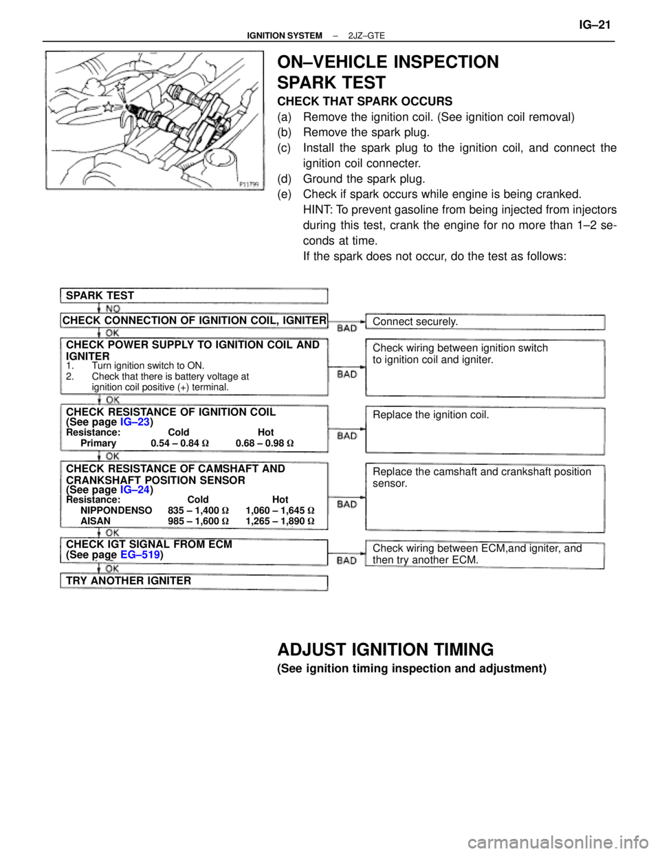
SPARK TEST
CHECK THAT SPARK OCCURS
(a) Remove the ignition coil. (See ignition coil removal)
(b) Remove the spark plug.
(c) Install the spark plug to the ignition coil, and connect the
ignition coil connecter.
(d) Ground the spark plug.
(e) Check if spark occurs while engine is being cranked.
HINT: To prevent gasoline from being injected from injectors
during this test, crank the engine for no more than 1±2 se-
conds at time.
If the spark does not occur, do the test as follows:
SPARK TEST
CHECK CONNECTION OF IGNITION COIL, IGNITER
CHECK POWER SUPPLY TO IGNITION COIL AND
IGNITER
1. Turn ignition switch to ON.
2. Check that there is battery voltage at
ignition coil positive (+) terminal.
CHECK RESISTANCE OF IGNITION COIL(See page IG±23)Resistance: Cold Hot
Primary 0.54 ± 0.84 �0.68 ± 0.98 �
CHECK RESISTANCE OF CAMSHAFT AND
CRANKSHAFT POSITION SENSOR
(See page IG±24)Resistance: Cold Hot
NIPPONDENSO 835 ± 1,400 �1,060 ± 1,645 �
AISAN 985 ± 1,600 �1,265 ± 1,890 �
CHECK IGT SIGNAL FROM ECM(See page EG±519)
TRY ANOTHER IGNITER
Connect securely.
Check wiring between ignition switch
to ignition coil and igniter.
Replace the ignition coil.
Replace the camshaft and crankshaft position
sensor.
Check wiring between ECM,and igniter, and
then try another ECM.
ADJUST IGNITION TIMING
(See ignition timing inspection and adjustment)
± IGNITION SYSTEM2JZ±GTEIG±21
Page 1159 of 2543
CAMSHAFT POSITION SENSORS
INSPECTION
NOTICE: ºColdº and ºHotº in the following sentences express
the temperature of the sensors themselves. ºColdº is from
±105C (145F) to 505C (1225F) and ºHotº is from 505C (1225F) to
1005C (2125F).
1. DISCONNECT CAMSHAFT POSITION SENSOR
CONNECTORS
2. INSPECT CAMSHAFT POSITION SENSOR RESISTANCE
Using an ohmmeter, measure the resistance between termi-
nals.
Resistance:
Cold
NIPPONDENSO
835±1,400 �
AISAN
985±1,600 �
Hot
NIPPONDENSO
1,060±1,645 �
AISAN
1,265±1,890 �
If the resistance is not as specified, replace the camshaft
position sensor.
3. RECONNECT CAMSHAFT POSITION SENSOR
CONNECTORS IG±24
± IGNITION SYSTEM(2JZ±GTE)
Page 1163 of 2543
CAMSHAFT POSITION SENSOR
COMPONENTS FOR REMOVAL AND
INSTALLATION
CAMSHAFT POSITION SENSOR
REMOVAL
Installation is in the reverse order of removal.
1. DISCONNECT IAC VALVE CONNECTOR
2. DISCONNECT AIR HOSE FROM IAC VALVE
3. REMOVE ENGINE HANGER
Remove the 2 bolts, ground strap and engine hanger.
Torque: 39 NVm (400 kgfVcm, 29 ftVlbf)
4. DISCONNECT CAMSHAFT POSITION SENSOR
CONNECTORS
5. REMOVE CAMSHAFT POSITION SENSORS
Remove the 4 bolts, 2 camshaft position sensors and 2 gas-
kets.
Torque: 6.4 NVm (65 kgfVcm, 56 in.Vlbf)
IG±28± IGNITION SYSTEM2JZ±GTE