Page 1325 of 2543

VALVE CLEARANCE INSPECTION AND
ADJUSTMENT (2JZ±GE)
HINT: Inspect and adjust the valve clearance when the en-
gine is cold.
1. REMOVE THROTTLE BODY AND INTAKE AIR
CONNECTOR ASSEMBLY
(See steps 1 to 9 in injector removal in SFI System)
2. DISCONNECT HIGH±TENSION CORDS FROM
CYLINDER HEAD COVERS
(See high±tension cords and cord clamps removal in
Ignition System)
3. REMOVE NO.3, NO.1 AND NO.2 CYLINDER HEAD
COVERS
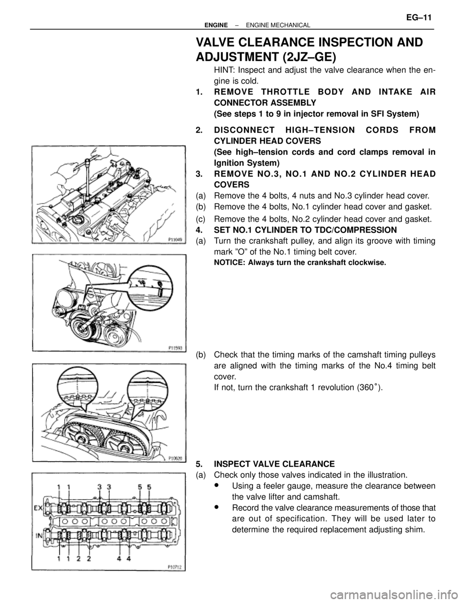
(a) Remove the 4 bolts, 4 nuts and No.3 cylinder head cover.
(b) Remove the 4 bolts, No.1 cylinder head cover and gasket.
(c) Remove the 4 bolts, No.2 cylinder head cover and gasket.
4. SET NO.1 CYLINDER TO TDC/COMPRESSION
(a) Turn the crankshaft pulley, and align its groove with timing
mark ºOº of the No.1 timing belt cover.
NOTICE: Always turn the crankshaft clockwise.
(b) Check that the timing marks of the camshaft timing pulleys
are aligned with the timing marks of the No.4 timing belt
cover.
If not, turn the crankshaft 1 revolution (360°).
5. INSPECT VALVE CLEARANCE
(a) Check only those valves indicated in the illustration.
wUsing a feeler gauge, measure the clearance between
the valve lifter and camshaft.
wRecord the valve clearance measurements of those that
are out of specification. They will be used later to
determine the required replacement adjusting shim.
± ENGINEENGINE MECHANICALEG±11
Page 1326 of 2543
Valve clearance (Cold):
Intake
.15±0.25 mm (0.006±0.010 in.)
Exhaust
.25±0.35 mm (0.010±0.014 in.)
(b) Turn the crankshaft pulley 1 revolution (360°), and align the
groove with timing mark ºOº of the No.1 timing belt cover.
(c) Check only the valves indicated as shown. Measure the valve
clearance. (See procedure in step (a))
6. ADJUST VALVE CLEARANCE
(a) Remove the adjusting shim.
wTurn the camshaft so that the cam lobe for the valve to
be adjusted faces up.
wTurn the valve lifter with a screwdriver so that the
notches are perpendicular to the camshaft.
wUsing SST (A), hold the camshaft as shown in the
illustration.
SST 09248±55040 (09248±05410)
wUsing SST (A), press down the valve lifter and place
SST (B) between the camshaft and valve lifter. Remove
SST (A).
SST 09248±55040 (09248±05410, 09248±05420)
HINT:
wApply SST (B) at slight angle on the side marked with
º7º, at the position shown in the illustration. EG±12
± ENGINEENGINE MECHANICAL
Page 1339 of 2543
7. SET NO.1 CYLINDER TO TDC/COMPRESSION
(a) Turn the crankshaft pulley, and align its groove with timing
mark ºOº of the No.1 timing belt cover.
NOTICE: Always turn the crankshaft clockwise.
(b) Check that the timing marks of the camshaft timing pulleys
are aligned with the timing marks of the No.4 timing belt
cover.
If not, turn the crankshaft 1 revolution (360°).
8. REMOVE TIMING BELT FROM CAMSHAFT TIMING
PULLEYS
HINT (Re±using timing belt): Place matchmarks on the timing
belt and camshaft timing pulleys as shown in the illustration.
(a) Alternately loosen the 2 bolts, and remove them, the
tensioner and dust boot.
(b) Disconnect the timing belt from the camshaft timing pulleys.
± ENGINEENGINE MECHANICALEG±25
Page 1340 of 2543
9. REMOVE CAMSHAFT TIMING PULLEYS
Using SST, remove the pulley bolt. Remove the 2 timing pul-
leys.
SST 09960±10010 (09962±01000, 09963±01000)
10. A/T:
DISCONNECT OIL COOLER TUBES
Remove the 2 bolts and hose clamps, and disconnect oil
cooler tubes.
11. REMOVE CRANKSHAFT PULLEY
(a) Using SST, loosen the pulley bolt.
SST 09213±70010, 09330±00021
(b) Remove the pulley bolt.
(c) Using SST, remove the pulley.
SST 09950±50010 (09954±05030, 09551±05010,
09552±05010, 09553±05020)
12. 2JZ±GE:
REMOVE PS PUMP FRONT BRACKET
Remove the 3 bolts, plate washer and pump front bracket. EG±26
± ENGINEENGINE MECHANICAL
Page 1342 of 2543

TIMING BELT COMPONENTS
INSPECTION
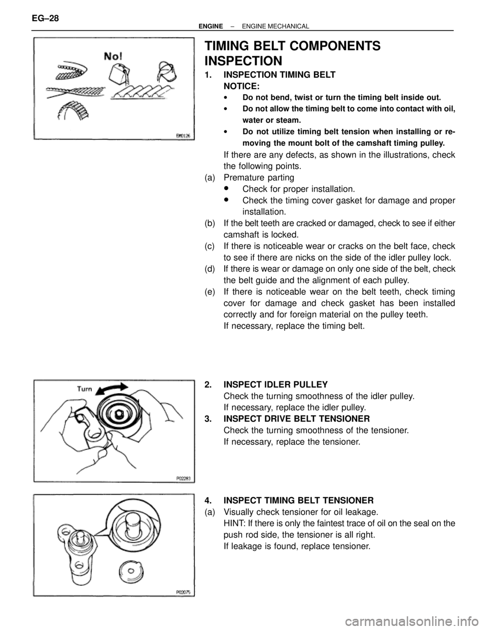
1. INSPECTION TIMING BELT
NOTICE:
wDo not bend, twist or turn the timing belt inside out.
wDo not allow the timing belt to come into contact with oil,
water or steam.
wDo not utilize timing belt tension when installing or re-
moving the mount bolt of the camshaft timing pulley.
If there are any defects, as shown in the illustrations, check
the following points.
(a) Premature parting
wCheck for proper installation.
wCheck the timing cover gasket for damage and proper
installation.
(b) If the belt teeth are cracked or damaged, check to see if either
camshaft is locked.
(c) If there is noticeable wear or cracks on the belt face, check
to see if there are nicks on the side of the idler pulley lock.
(d) If there is wear or damage on only one side of the belt, check
the belt guide and the alignment of each pulley.
(e) If there is noticeable wear on the belt teeth, check timing
cover for damage and check gasket has been installed
correctly and for foreign material on the pulley teeth.
If necessary, replace the timing belt.
2. INSPECT IDLER PULLEY
Check the turning smoothness of the idler pulley.
If necessary, replace the idler pulley.
3. INSPECT DRIVE BELT TENSIONER
Check the turning smoothness of the tensioner.
If necessary, replace the tensioner.
4. INSPECT TIMING BELT TENSIONER
(a) Visually check tensioner for oil leakage.
HINT: If there is only the faintest trace of oil on the seal on the
push rod side, the tensioner is all right.
If leakage is found, replace tensioner. EG±28
± ENGINEENGINE MECHANICAL
Page 1345 of 2543

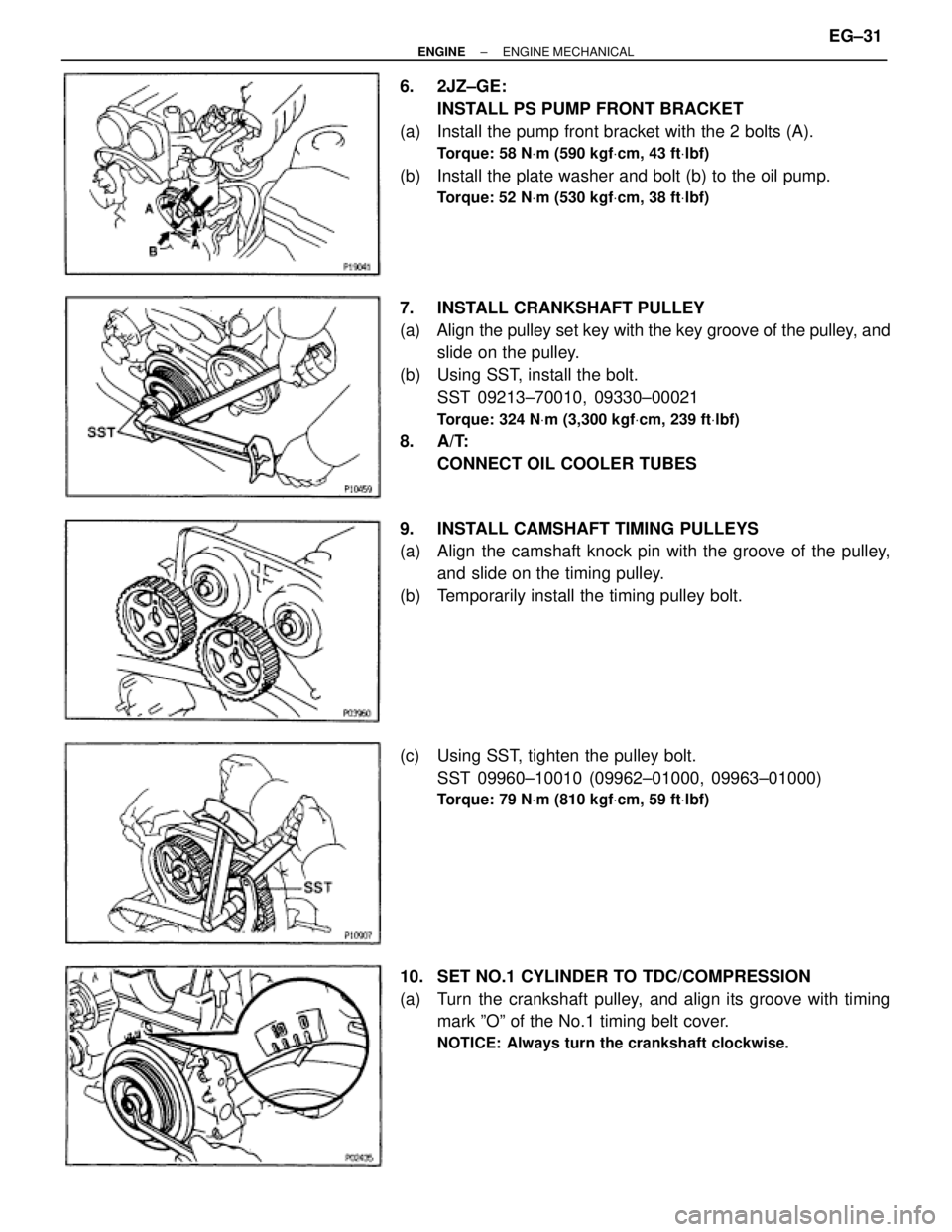
6. 2JZ±GE:
INSTALL PS PUMP FRONT BRACKET
(a) Install the pump front bracket with the 2 bolts (A).
Torque: 58 NVm (590 kgfVcm, 43 ftVlbf)
(b) Install the plate washer and bolt (b) to the oil pump.
Torque: 52 NVm (530 kgfVcm, 38 ftVlbf)
7. INSTALL CRANKSHAFT PULLEY
(a) Align the pulley set key with the key groove of the pulley, and
slide on the pulley.
(b) Using SST, install the bolt.
SST 09213±70010, 09330±00021
Torque: 324 NVm (3,300 kgfVcm, 239 ftVlbf)
8. A/T:
CONNECT OIL COOLER TUBES
9. INSTALL CAMSHAFT TIMING PULLEYS
(a) Align the camshaft knock pin with the groove of the pulley,
and slide on the timing pulley.
(b) Temporarily install the timing pulley bolt.
(c) Using SST, tighten the pulley bolt.
SST 09960±10010 (09962±01000, 09963±01000)
Torque: 79 NVm (810 kgfVcm, 59 ftVlbf)
10. SET NO.1 CYLINDER TO TDC/COMPRESSION
(a) Turn the crankshaft pulley, and align its groove with timing
mark ºOº of the No.1 timing belt cover.
NOTICE: Always turn the crankshaft clockwise.
± ENGINEENGINE MECHANICALEG±31
Page 1346 of 2543

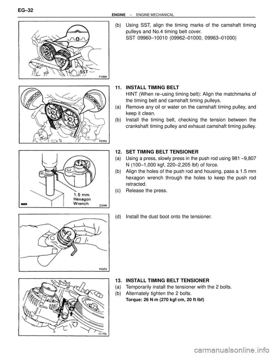
(b) Using SST, align the timing marks of the camshaft timing
pulleys and No.4 timing belt cover.
SST 09960±10010 (09962±01000, 09963±01000)
11. INSTALL TIMING BELT
HINT (When re±using timing belt): Align the matchmarks of
the timing belt and camshaft timing pulleys.
(a) Remove any oil or water on the camshaft timing pulley, and
keep it clean.
(b) Install the timing belt, checking the tension between the
crankshaft timing pulley and exhaust camshaft timing pulley.
12. SET TIMING BELT TENSIONER
(a) Using a press, slowly press in the push rod using 981 ±9,807
N (100±1,000 kgf, 220±2,205 lbf) of force.
(b) Align the holes of the push rod and housing, pass a 1.5 mm
hexagon wrench through the holes to keep the push rod
retracted.
(c) Release the press.
(d) Install the dust boot onto the tensioner.
13. INSTALL TIMING BELT TENSIONER
(a) Temporarily install the tensioner with the 2 bolts.
(b) Alternately tighten the 2 bolts.
Torque: 26 NVm (270 kgfVcm, 20 ftVlbf)
EG±32± ENGINEENGINE MECHANICAL
Page 1359 of 2543
33. REMOVE NO.3, NO.1 AND NO.2 CYLINDER HEAD
COVERS
(a) Remove the PCV valve.
(b) Remove the 4 bolts, 4 nuts and No.3 cylinder head cover.
(c) Remove the 4 bolts, No.1 cylinder head cover and gasket.
(d) Remove the 4 bolts, No.2 cylinder head cover and gasket.
34. REMOVE CAMSHAFT TIMING PULLEYS
Hold the hexagon portion of the camshaft with a wrench, and
remove the pulley mounting bolt and camshaft pulley.
35. REMOVE NO.4 TIMING BELT COVER
Remove the 4 bolts and timing belt cover.
36. REMOVE CAMSHAFTS
(a) Uniformly loosen and remove the 4 No.1 bearing cap bolts.
(b) Using a screwdriver, pry out the 2 No.1 camshaft bearing
caps and oil seals.
NOTICE: Be careful not to damage the cap. Tape the screwdriv-
er tip.
± ENGINEENGINE MECHANICALEG±45