Page 2002 of 2543
.
������")
If a malfunction code is displayed during the diagnostic trouble code check in test mode, check the circuit for
that code listed in the table below (Proceed to the page given for that circuit).
�������������������� �
������������������� �
������������������� ��������������������Trouble Area
������� �
������ �
������ �������
Malfunction
Indicator
Lamp*
1
������ �
����� �
����� ������Memory*2
������ �
����� �
����� ������See page
�������������������� �
������������������� ��������������������
Trouble Area
���� �
��� ����
Normal
Mode���� �
��� ����
Test
Mode������ �
����� ������
Memory
������ �
����� ������
See page
�������������������� �
������������������� �
������������������� ��������������������
±
���� �
��� �
��� ����
±
���� �
��� �
��� ����
±
������ �
����� �
����� ������
±
������ �
����� �
����� ������
±
�������������������� �
������������������� �
������������������� �
������������������� �
������������������� ��������������������
�Open or short in crankshaft position sensor, camshaft
position sensor No.1, No.2 circuit
�Crankshaft position sensor
�Camshaft position sensor No.1, No.2
�Starter
�ECM
���� �
��� �
��� �
��� �
��� ����
ON
���� �
��� �
��� �
��� �
��� ����
N.A.
������ �
����� �
����� �
����� �
����� ������
�
������ �
����� �
����� �
����� �
����� ������
EG±515
�������������������� �
������������������� �
������������������� ��������������������
�Open or short in crankshaft position sensor circuit
�Crankshaft position sensor
�ECM
���� �
��� �
��� ����ON
���� �
��� �
��� ����N.A.
������ �
����� �
����� ������
������ �
����� �
����� ������
�������������������� �
������������������� �
������������������� �
������������������� �
������������������� ��������������������
�Open or short in crankshaft position sensor circuit
�Mechanical system malfunction (skipping teeth of
timing belt, belt stretched)
�Crankshaft position sensor
�ECM
���� �
��� �
��� �
��� �
��� ����
N.A.
���� �
��� �
��� �
��� �
��� ����
ON
������ �
����� �
����� �
����� �
����� ������
�
������ �
����� �
����� �
����� �
����� ������
EG±518
�������������������� �
������������������� �
������������������� �
������������������� ��������������������
�Mechanical system malfunction (skipping teeth of
timing belt, belt stretched)
�Camshaft position sensor No.1, No.2
�ECM
���� �
��� �
��� �
��� ����
ON
���� �
��� �
��� �
��� ����
N.A.
������ �
����� �
����� �
����� ������
������ �
����� �
����� �
����� ������
�������������������� �
������������������� �
������������������� ��������������������
�Open or short in IGF circuit from igniter to ECM
�Igniter
�ECM
���� �
��� �
��� ����
ON
���� �
��� �
��� ����
N.A.
������ �
����� �
����� ������
�
������ �
����� �
����� ������
EG±519
�������������������� �
������������������� �
������������������� ��������������������
�ECM
���� �
��� �
��� ����
ON
���� �
��� �
��� ����
N.A.
������ �
����� �
����� ������
X
������ �
����� �
����� ������
EG±524
*1, 2: See page EG±502.
± ENGINE2JZ±GTE ENGINE TROUBLESHOOTINGEG±495
Page 2022 of 2543
 are mounted on the intake side of the cylinder head
and the crankshaft position sensor (NE signal) is mounted on the oil pump body. Th")
CIRCUIT DESCRIPTION
Camshaft position sensors (G1 and G2 signals) are mounted on the intake side of the cylinder head
and the crankshaft position sensor (NE signal) is mounted on the oil pump body. These sensors consist
of a timing rotor and pick up coil.
The G1, G2 timing rotors have 1 tooth each on their outer circumference and are mounted on the intake
camshaft.
When the intake camshaft rotates, the protrusion on the timing rotors and the air gap on the pick up
coil change, causing fluctions in the magnetic field and generating an electromotive force in the pick
up coil.
The NE timing rotor has 12 teeth and is mounted on the crankshaft. The NE signal sensor generates
12 NE signals per engine revolution. The ECM detects the standard crankshaft angle based on the G1,
G2 signals, and the actual crankshaft angle and the engine speed by the NE signals.
DTC No.Diagnostic Trouble Code Detecting ConditionTrouble Area
No ªNEº or ªG1º and ªG2º signal to ECM for 2 sec.
or more after cranking
�Open or short in crankshaft position
sensor, camshaft position sensor No.1, No.2
circuit
�Crankshaft position sensor
�Camshaft position sensor No.1, No.2
�Starter
�ECM
CIRCUIT INSPECTION
DTC 12 G NE Signal Circuit (No.1)
± ENGINE2JZ±GTE ENGINE TROUBLESHOOTINGEG±515
Page 2023 of 2543
INSPECTION PROCEDURE
(See page IG±30).
Check crankshaft position sensor, camshaft position sensors No.1, No.2.
For crankshaft position sensor, remove crankshaft posi-
tion sensor (See page IG±30).
For camshaft position sensor No.1, No.2, disconnect
camshaft position sensor No.1 No.2 connectors.
Measure resistance of crankshaft position sensor, cam-
shaft position sensor No.1 and No.2.
Camshaft
Position Sensor
No.1 and No.2
Camshaft
Position
Sensor
ªColdº is from Ð 10°C (14°F) to 50°C (122°F) and ªHotº
is from 50°C (122°F) to 100°C (212°F).
EG±516± ENGINE2JZ±GTE ENGINE TROUBLESHOOTING
Page 2024 of 2543
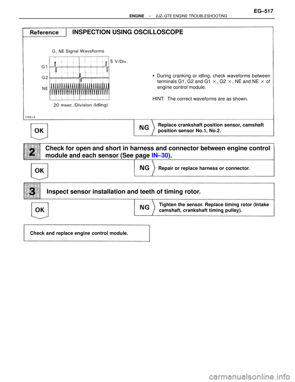
Check for open and short in harness and connector between engine control
module and each sensor (See page IN±30).
�During cranking or idling, check waveforms between
terminals G1, G2 and G1 �, G2 �, NE and NE � of
engine control module.
HINT: The correct waveforms are as shown.
Inspect sensor installation and teeth of timing rotor.
INSPECTION USING OSCILLOSCOPE
Replace crankshaft position sensor, camshaft
position sensor No.1, No.2.
Tighten the sensor. Replace timing rotor (Intake
camshaft, crankshaft timing pulley).
Check and replace engine control module.
Repair or replace harness or connector.
± ENGINE2JZ±GTE ENGINE TROUBLESHOOTINGEG±517
Page 2025 of 2543

CIRCUIT DESCRIPTION
Refer to G, NE signal circuit (No.1) on page EG±515
����� �����DTC No.������������������ ������������������Diagnostic Trouble Code Detecting Cond")
DTC 13 G NE Signal Circuit (No.2)
CIRCUIT DESCRIPTION
Refer to G, NE signal circuit (No.1) on page EG±515
����� �����DTC No.������������������ ������������������Diagnostic Trouble Code Detecting Condition��������������� ���������������Trouble Area
����� �
���� �
���� �
���� �����
������������������ �
����������������� �
����������������� �
����������������� ������������������
No NE signal to ECM for 0.1 sec. or more at
1,000 rpm or more
��������������� �
�������������� �
�������������� �
�������������� ���������������
�Open or short in crankshaft position
sensor circuit
�Crankshaft position sensor
�ECM
����� �
���� �
���� �
���� �
���� �
���� �����
13
������������������ �
����������������� �
����������������� �
����������������� �
����������������� �
����������������� ������������������
NE signal does not pulse 12 times to ECM
during the interval between G1 and G2 pulses
��������������� �
�������������� �
�������������� �
�������������� �
�������������� �
�������������� ���������������
�Open or short in crankshaft position
sensor circuit
�Mechanical system malfunction (skipping
teeth of timing belt, belt stretched)
�Crankshaft position sensor
�ECM
����� �
���� �
���� �
���� �����
������������������ �
����������������� �
����������������� �
����������������� ������������������
Deviation in G (G1, G2) and NE signal
Continues for 3 sec. during idling
throttle fully closed after engine warmed up��������������� �
�������������� �
�������������� �
�������������� ���������������
�Mechanical system malfunction (skipping
teeth of timing belt, belt stretched)
�Camshaft position sensor No. 1, No.2
�ECM
INSPECTION PROCEDURE
Inspect sensor installation. Check if any teeth of NE signal plate are broken.
Tighten sensor.
Replace timing rotor.
Adjust valve timing (repair or replace timing belt).
Check valve timing (Check for loose and jumping teeth of timing belt
(See page EG±33)).
Check for intermittent problems.
(See page EG±505)
EG±518± ENGINE2JZ±GTE ENGINE TROUBLESHOOTING
.
Check crankshaft position sensor, camshaft position sensors No.1, No.2.
For crankshaft position sensor, remove crankshaft posi-
tion sensor (See page IG±30).
F")